PORTABLE 3D PRINTER-SCANNER
STEP 11: OUTPUT DEVICES
OBJECTIVE
- Add an output device to a microcontroller board you've designed and program it to do something.
Fabricate on of the "hello world" output examples board(s)
- Add an output device to a microcontroller board you've designed and program it to do something.
Fabricate on of the "hello world" output examples board(s)
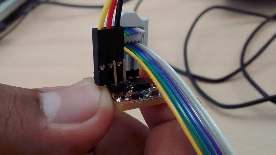
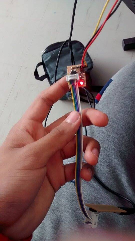
I put extra tin in my board's surface for recognizing it later (as you can see below).
PROGRAMMING
Program them (in as many languages as possible)
Program them (in as many languages as possible)
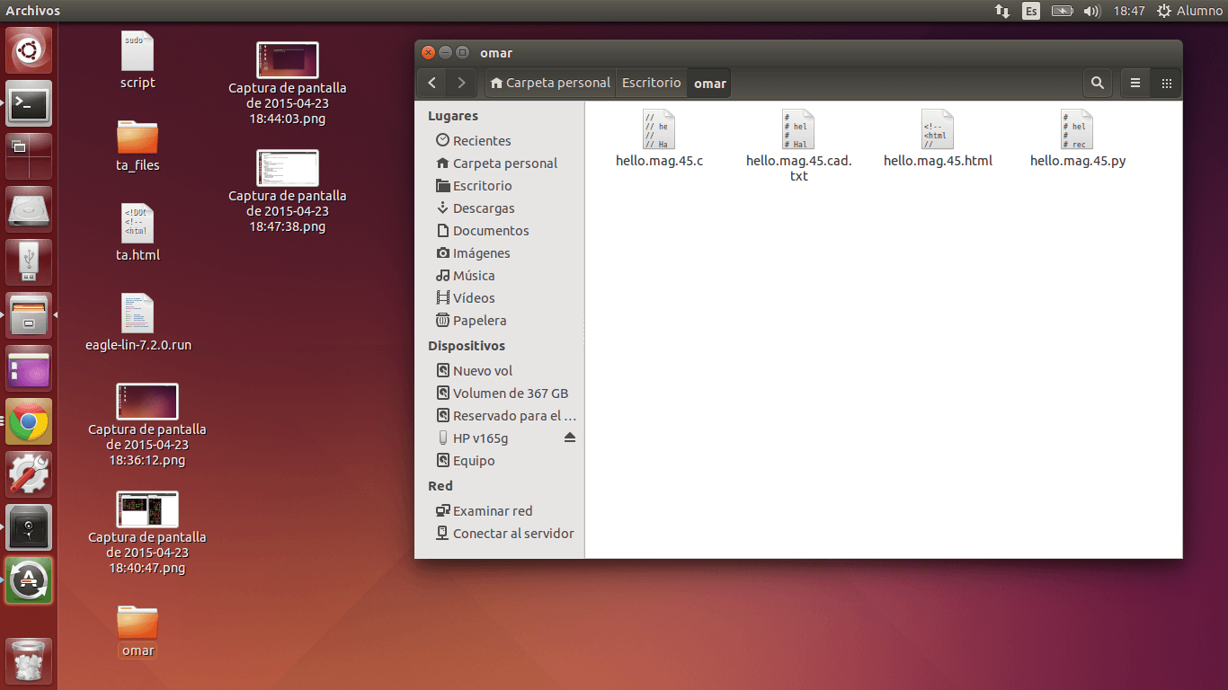
1. I downloaded the archives of the sensor I was going to build (RGB) in a New File inside my Desktop that I named "omar":
2.
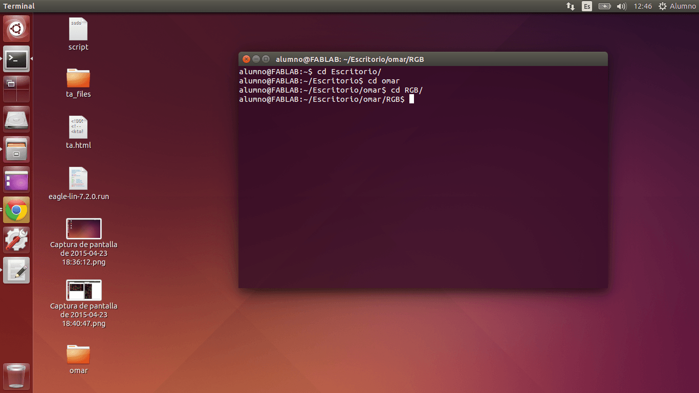
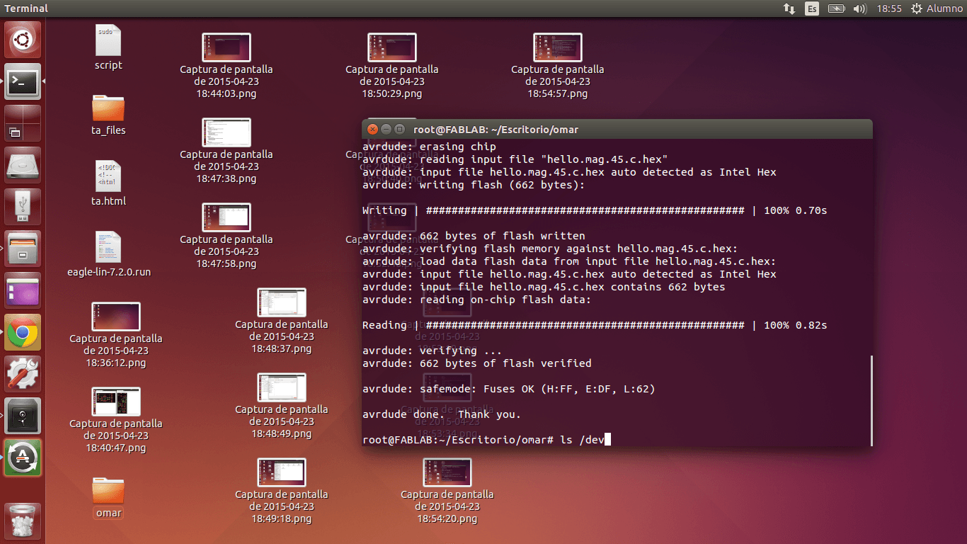
I opened the Terminal. I wrote cd Escritorio (Desktop in Spanish), then
cd omar, next cd RGB in order to open and run the downloaded archives.
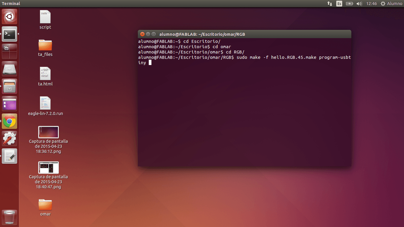
3. I wrote sudo make -f hello.RGB.make program-usbtiny in order to run the C code of the RGB Output.
4.
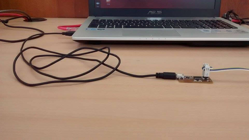
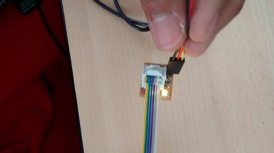
I connected the Fab ISP and the RGB Output with the larger side
from each of the 3x2 pins pointing in the same direction.
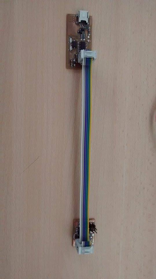
5. I connected the USB cable to the Fab ISP
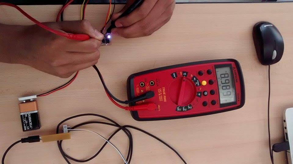
6. I connected the 2x2 pins of the RGB Output to a battery
8.
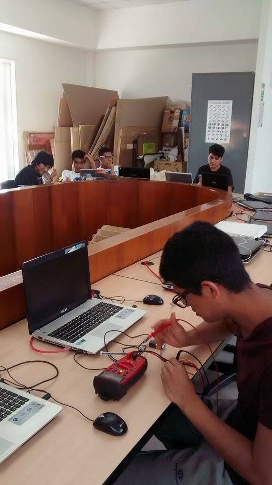
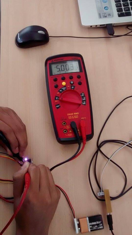
When I run the code, it appeared "Error 1". Therefore, I used the
Multimeter to identify the problem and I realized that the circuits
near the 2x2 pins that did not reach the regulator did not show a
number between 8.9 and 9-1 in the Multimeter and the circuits that
passed the regulator did not show a number between 4.9 and 5.1 in the
Multimeter.
9. I changed the regulator and the Multimeter showed what I needed.
9. I changed the regulator and the Multimeter showed what I needed.
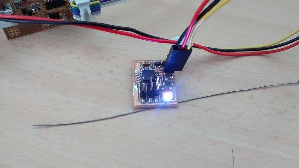
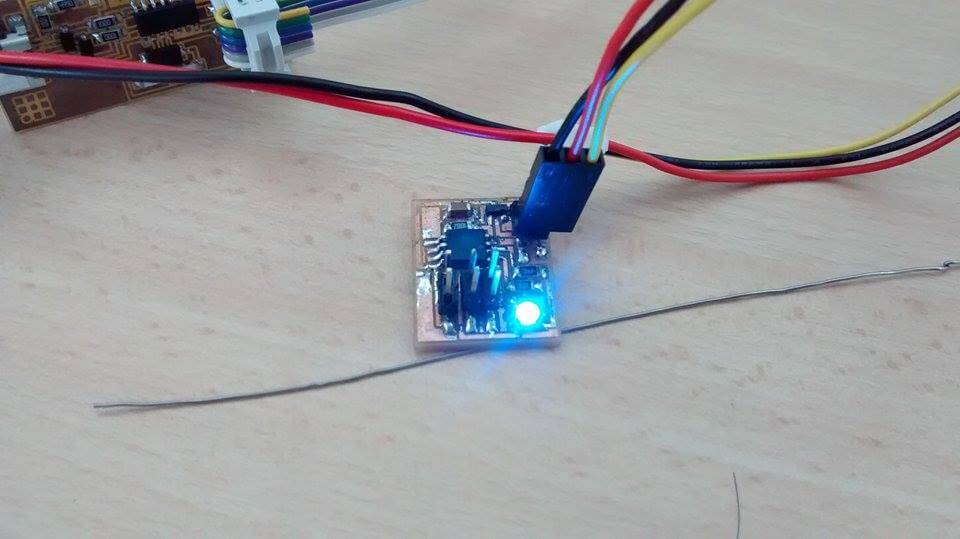
7. The code run!!!
8. The RGB Output was changing its colours, it was working!
PARTS & FUNCTIONS
GENERAL FUNCTION
GENERAL FUNCTION
Document what each board does, what protocol it uses, what you learned
- RGB SENSOR: Changes the color of a LED light to practically any color (all colors created by Red, Green and Blue light combinations)
- I learn that you need to check connections, when you start doing power electronics
- Each of this pixels contatins 3LEDs
-Regulator transforms 6V into 5V
- Power goes to processer
- Here a pin is selectevely ground
- Blue is less efficient; thus we need use more current
- The intensity varies by pulse in modulating (Faster than your eye can see it)