PORTABLE 3D PRINTER-SCANNER
STEP 10: INPUT DEVICES
Home
OBJECTIVE
- Measure something: Add a sensor to a microcontroller board that you've designed and read it
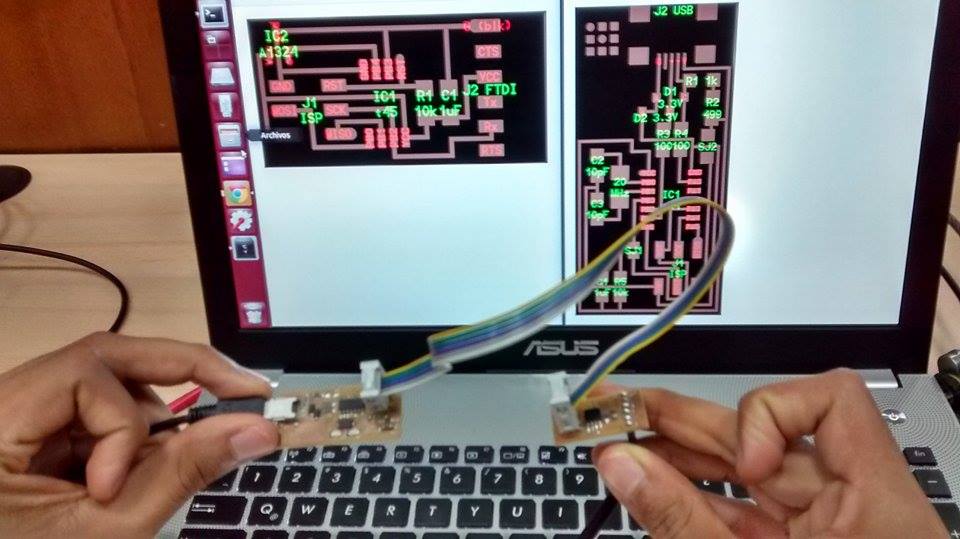
CUT, SOLD AND CONNECT
Fabricate one of the "hello world" input example boards
1. I cut the Magnetic Force Input in the Roland Modela and solded it. I should mention that now I can sold a lot faster, 30 minutes instead of 5 hours!
2. I stapled two gray heads at each side of set of colorful cables
3. I put a metal cable in one of the holes of each head
4. I opened the Fab ISP png from the Electronics Production Week and the Magnetic Force Input from the Input Devices Week, to identify the GND side of each of the boards
4. I used the Multimeter to identify which pin of the first board correspond to the second board in terms of current flow. Therefore, I put the Multimeter in current mode, put metal cables in each board's GND side of each end of the multicolour cable and touched each of them with the Multimeter. If there was a sound, there was current flow; otherwise I should change the position of one of the cable metals to the only hole left in one of the board's GND side.
5. I connected the Bridge with the FabISP meeting the correspondance requirement.
DOWNLOAD AND SET UP
Program them (in as many languages as possible)
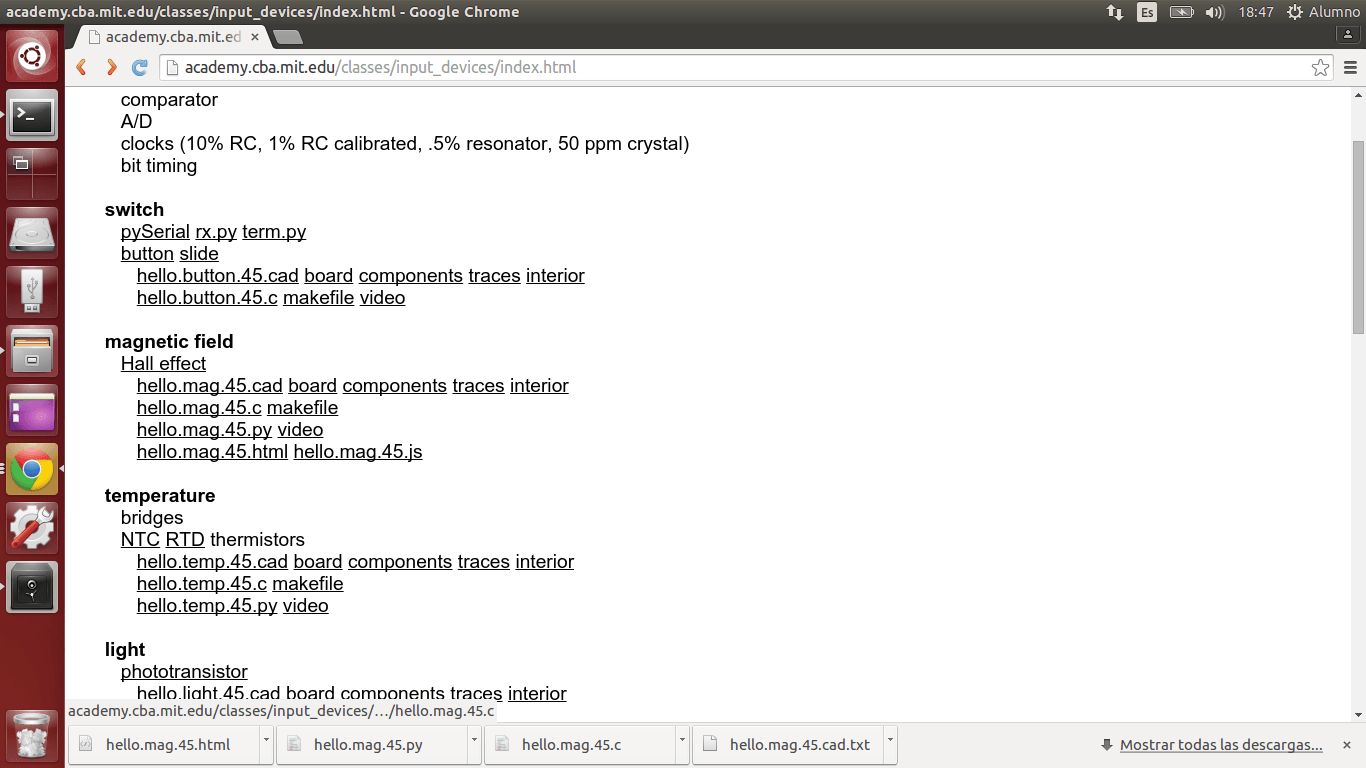
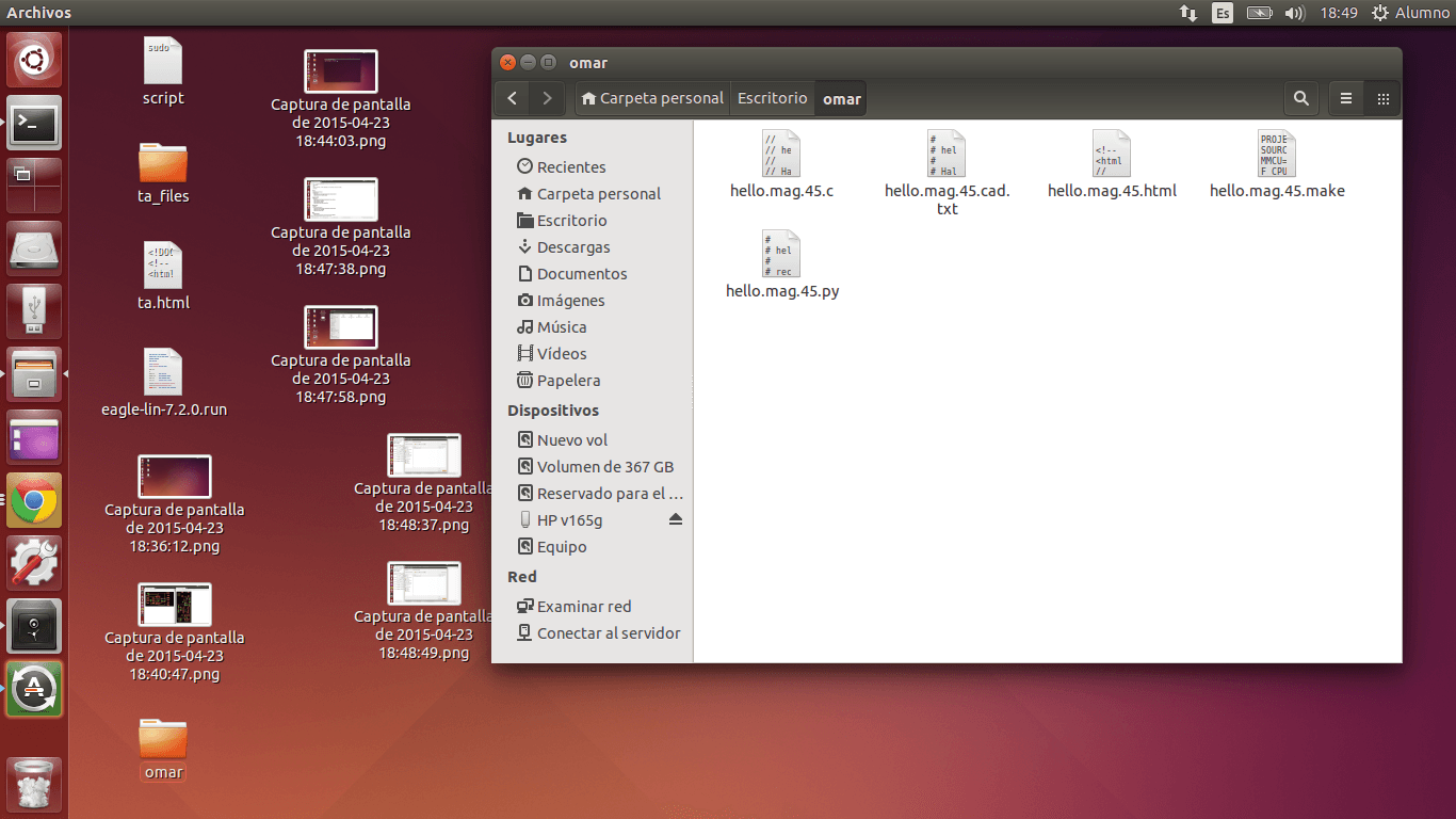
1. I downloaded the archives of the sensor I was going to build in a New File inside my Deskop that I named "omar":
- hello.mag.45.c
- hello.mag.45.cad.txt
- hello.mag.45.html
- hello.mag.45.make
- hello.mag.45.py
- hello.mag.45.cad.txt
- hello.mag.45.html
- hello.mag.45.make
- hello.mag.45.py
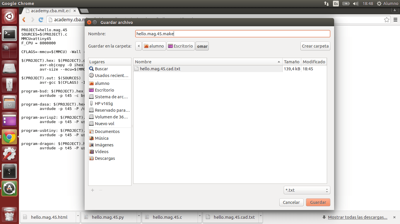
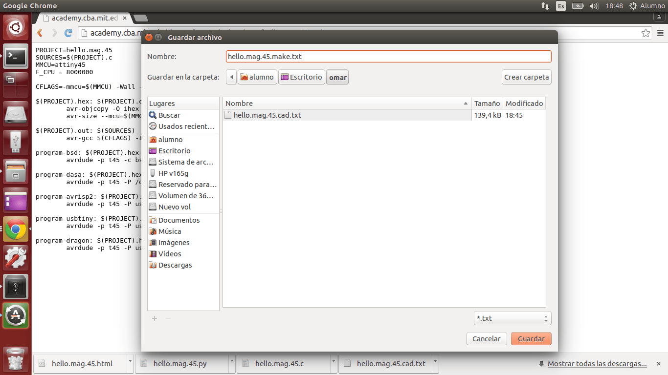
2.
When I was downloading hello.mag.45.make, I erased the ".txt" in the
bar above just to make sure that the archive was going to be readed as
".make"
3. I clicked in the red circle in the top left and wrote
"Terminal". I opened the black rectangle in the left. I wrote "sudo
bash" and Fab Tecsup's password.
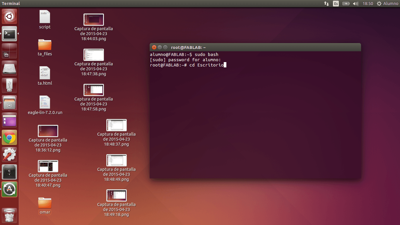
4. In
order to let the machine know where was the archive that I wanted to
run, I wrote "cd Escritorio" (Desktop) and then "cd omar"

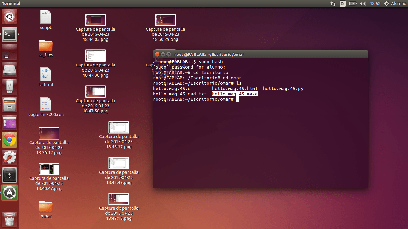
5. I wrote "ls" in order to make sure that I had all the archives I downloaded in the first step, and yes, I had them.
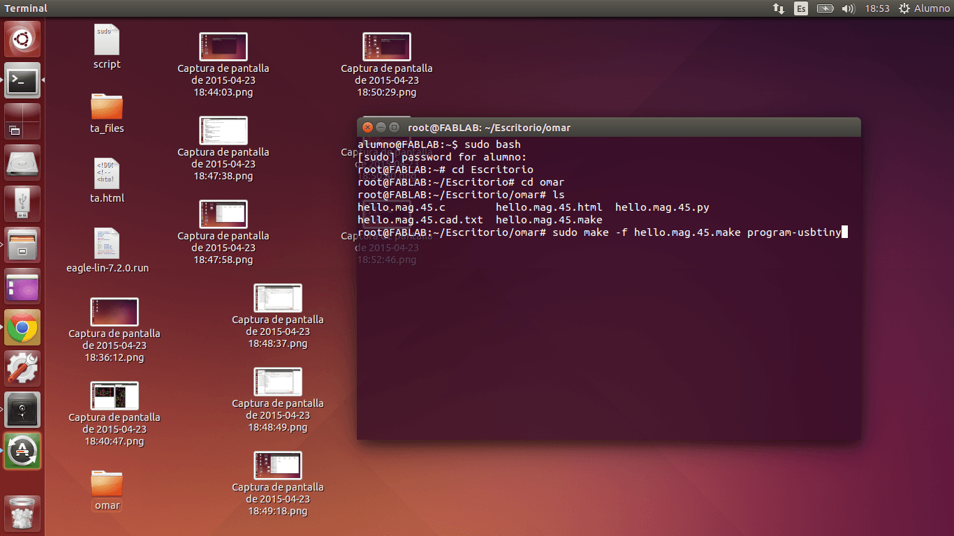
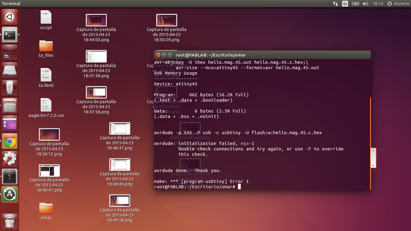
6. I wrote the command "sudo make -f hello.mag.45.make program.usbtiny" for running my sensor's program
7.
Sadly, may program did not work our. "Error 1" appeared, so I read the
Terminal and found this line: "Double check connections and try again
(...)". Therefore, the code was running, but the computer did not read
my Input.
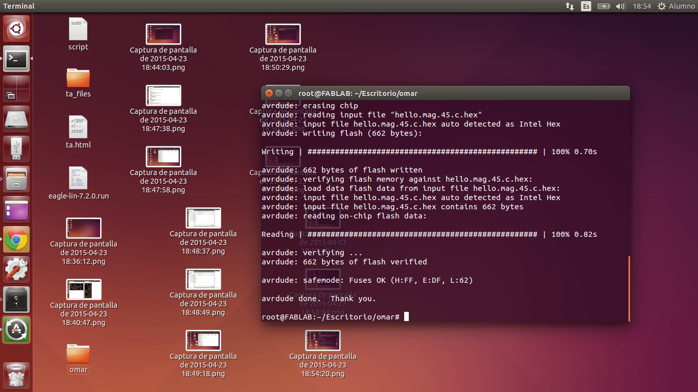
8.
Later, I realized that this was due to the fact that my regulator was
overheated, that my board did not work (I will explain later how to
realize if it is only a piece that does not work or the entire board),
I connected the ISP and my FTDI again and the code run ok.
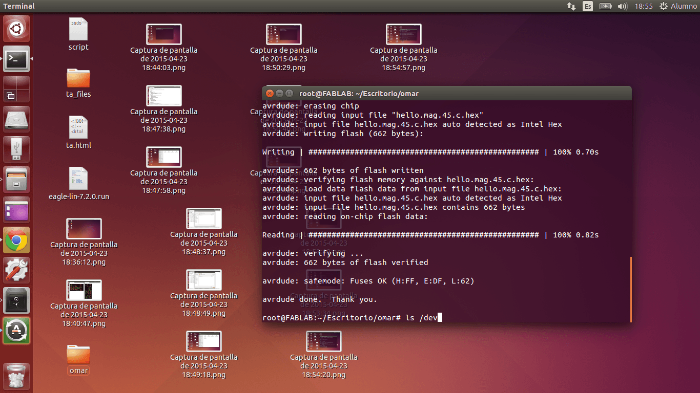
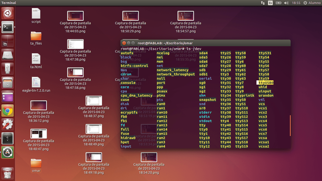
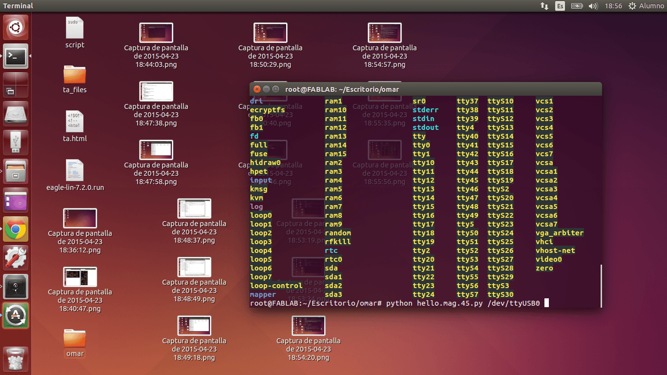
9. I wrote "les /dev"
in order to identify the name of the port where my Input device was
connected. After scrolling the Terminal window, I realized that the
port name was ttyUSB0.
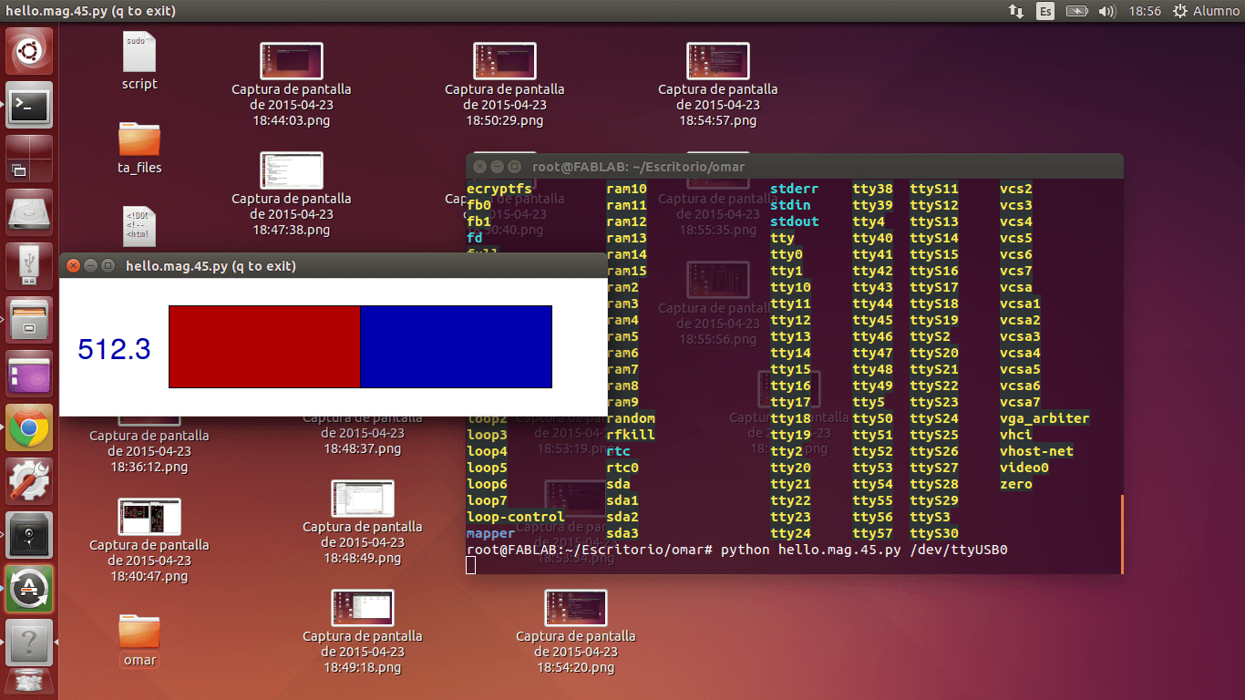
10. I wrote the following command in Python language to show the code rules graphically: python hello.mag.45.py /dev/ttyUSB0.
11.
The magnetic force measurement program run successfully! I took a
magnet from the Roland Modela to change the values displayed in the
Python Window.
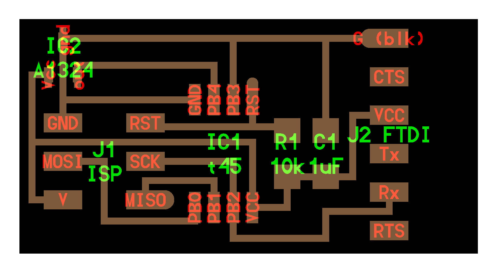
PARTS & FUNCTIONS
Document each sensor, what it does, what you learned
GENERAL FUNCTION
SPECIFIC FUNCTION (OPTIONAL)
...Below is the information I summarized from Jose de Lazarte's classes and Isaac Roble's feedback. It specifies what every part represented by green words does.
1. ISP 2x3 pins:
- Physical channel that allows the program to be saved (or flashed, because ATTiny 45's memory is flash type) in the ATTiny 45
2. ATTiny 45:
- Receives magnetic hall sensor's signals (data) through 'OUT' pin of the hall sensor and processes them in a way that can be read by the computer.
3. Resistence (pull up):
- As it goes to 'RESET and VCC' pins it works as a pull up.
- A resistence is needed, because if one presses a push-button very fast, it burns. Resistor allows the current to increase and decrease constantly, not randomly.
4. CAPACITOR:
- When there is charge in the board, it stores charges
- When there is NOT charge in the board, it releases charge
5. SENSOR:
- Provides information about the variations of magnetic fields.
6. FTDI pins:
6.1. Tx (transmission): Allows computer information to reach the ATTiny45; however, for this case, Tx is not used.
6.2. Rx (reception): Allows signals to go to the computer
6.3. VCC: 5V of USB terminal enter through this pin
6.4.RTS: Allows Rx pin to accept data
6.5. CTS: Allows Tx pin to move data
CONCLUSIONS
- I learned (in detail) how the information flows from the magnetic field board and the computer
- Thus, I learned how to connect a FTDI cable to my magnetic field board without burning my board.
- I learned how to download a code that employs Serial communication to a board made by me.
- I learned that an interphase is a graphical representation of a code that employs Serial communication.
GENERAL FUNCTION
MAGNETIC FIELD SENSOR: Measures variations in the magnetic field of objects
...Below is the information I summarized from Jose de Lazarte's classes and Isaac Roble's feedback. It specifies what every part represented by green words does.
1. ISP 2x3 pins:
- Physical channel that allows the program to be saved (or flashed, because ATTiny 45's memory is flash type) in the ATTiny 45
2. ATTiny 45:
- Receives magnetic hall sensor's signals (data) through 'OUT' pin of the hall sensor and processes them in a way that can be read by the computer.
3. Resistence (pull up):
- As it goes to 'RESET and VCC' pins it works as a pull up.
- A resistence is needed, because if one presses a push-button very fast, it burns. Resistor allows the current to increase and decrease constantly, not randomly.
4. CAPACITOR:
- When there is charge in the board, it stores charges
- When there is NOT charge in the board, it releases charge
5. SENSOR:
- Provides information about the variations of magnetic fields.
6. FTDI pins:
6.1. Tx (transmission): Allows computer information to reach the ATTiny45; however, for this case, Tx is not used.
6.2. Rx (reception): Allows signals to go to the computer
6.3. VCC: 5V of USB terminal enter through this pin
6.4.RTS: Allows Rx pin to accept data
6.5. CTS: Allows Tx pin to move data
CONCLUSIONS
- I learned (in detail) how the information flows from the magnetic field board and the computer
- Thus, I learned how to connect a FTDI cable to my magnetic field board without burning my board.
- I learned how to download a code that employs Serial communication to a board made by me.
- I learned that an interphase is a graphical representation of a code that employs Serial communication.