FabLab Unal Medellin
This Lab is located in the Arts and Architecture school of the Universidad Nacional Medellin, Colombia.
This Lab is located in the Arts and Architecture school of the Universidad Nacional Medellin, Colombia.
The "fab team" began this adventure, downloading the original files of the cardboard CNC in order to fabricate machine. but, we quickly saw some initial errors in the digital models, that affect in somehow the prototype process.
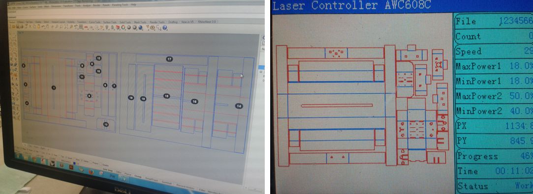
We checked the cut vectors in relationship with the original downloaded models , and in this case we also found some errors as double lines, and open vectors (nonoptimal for the laser cutting process), for this reason we did the first modifications in the digital files.
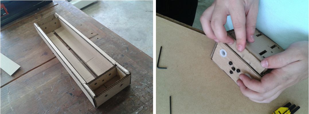
The material thickness didn't work well for us; we realized that there was "problems" with the original model (at this time we don't know if we have the correct files). The cardboard prototype gave us serious problems assembling it, for that reason we decided modeling our digital prototype... of course based in the original downloaded digital model. Redrawing the machine we understood much more the systems
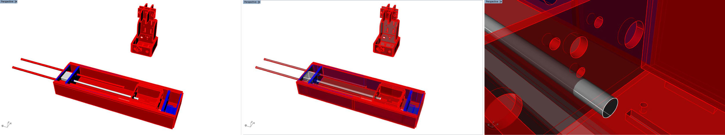
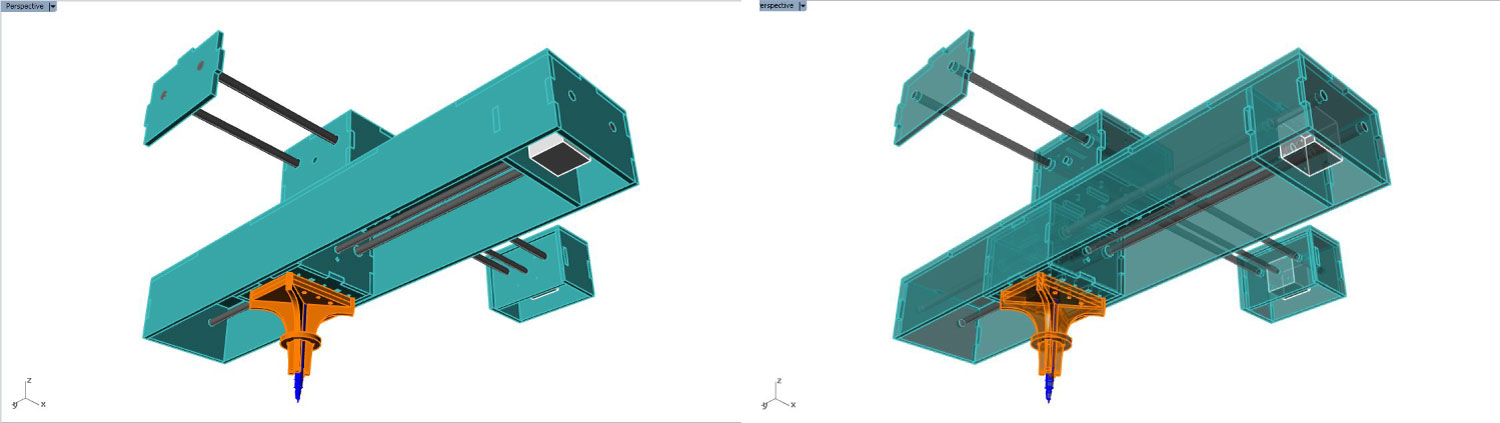
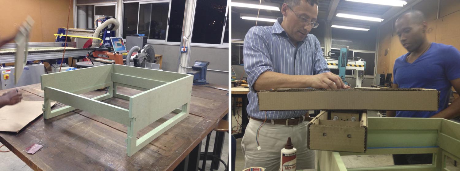
Having in mind all the previous "inconvenients", and thinking on how to improve our prototype, we designed a framework in MDF-RH/15 mm (leftover fab-material) for stiffening the CNC machine.
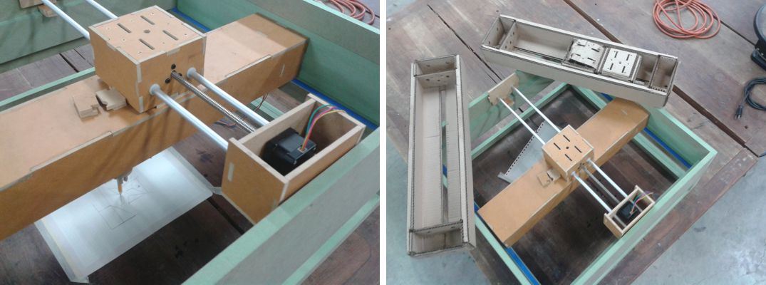
The picture above shows the bottom part of the digital model.
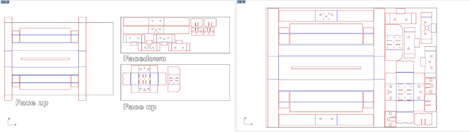
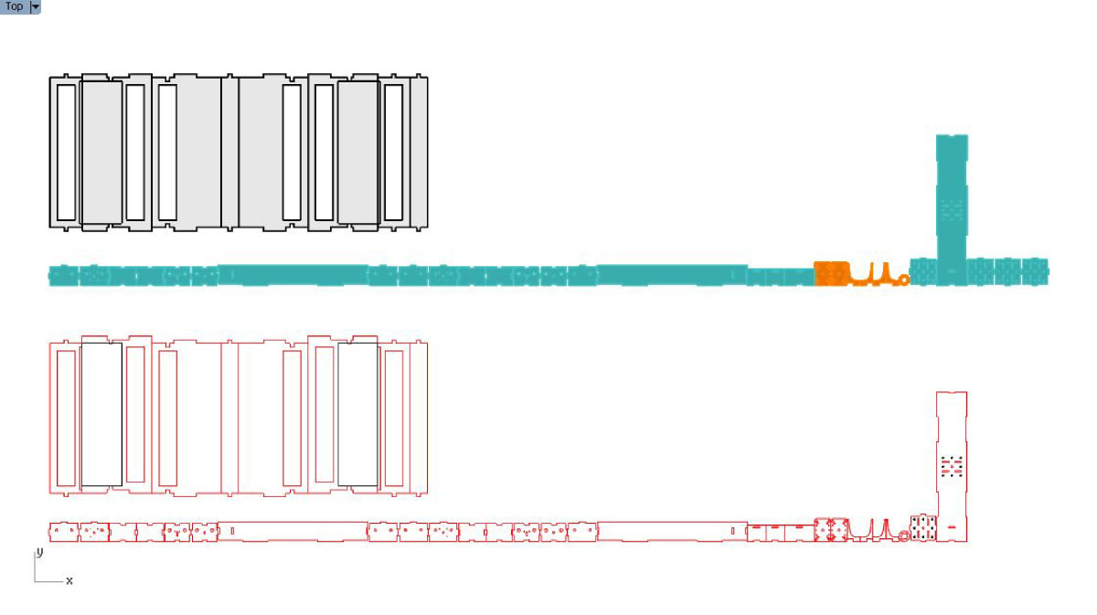
Our new machine was ready for fabrication. We nest the vectors in a 1mx1m cardboard format. We made two files for the same cut. One file is the top and the other is the bottom of the same file. Later we laser cut the files and made the frame work in the Shopbot CNC machine.

Although the cardboard machine "worked" we were not happy with the result. There was a few problems that we could solve with a new material. Again, we decided to make a new CNC in a rigid material, (again with left overs of the fab lab process). The material chosen was MDF of 5 mm. We made again the files based on the original downloaded model.
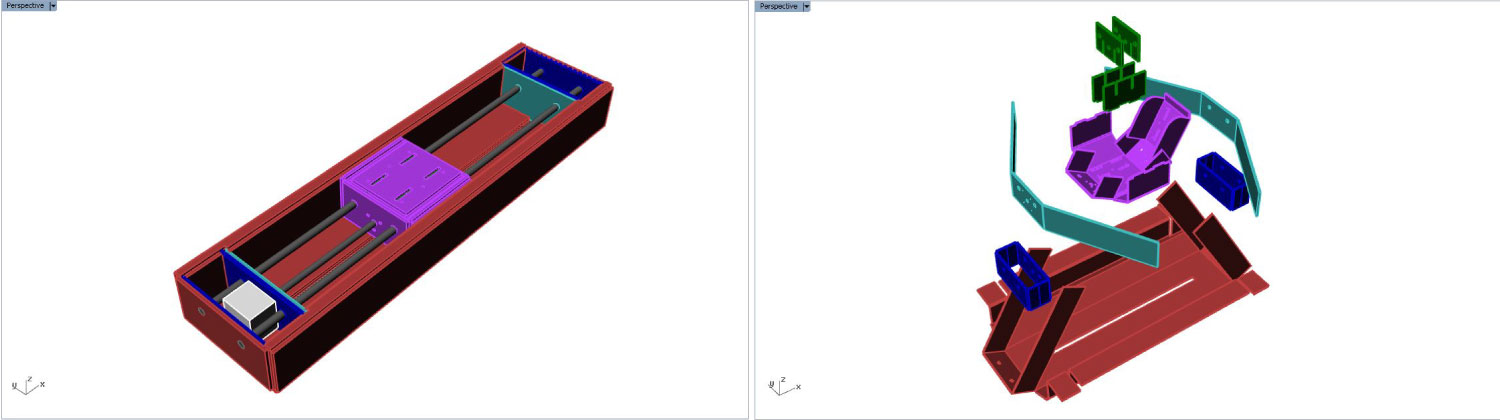
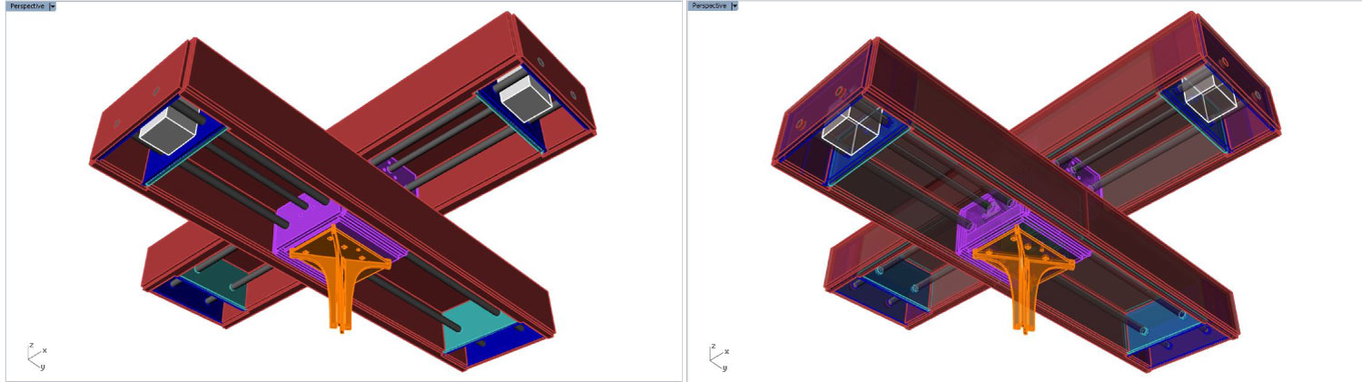
Machine parts and systems.

Also we designed a the pencil case, because we decided that our machine will a plotter prototype.
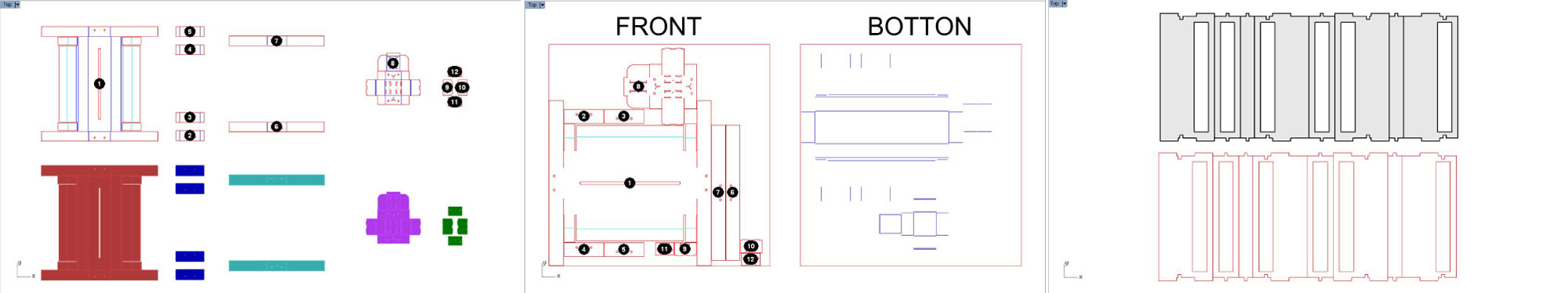
This are the digital files "vectors" for the cut process in the shopbot machine.
The fab machine was an easy cnc card board machine that was composed by two or three inter sliding boxes. Our first work was to download the files provided by fab academy, put them to the laser cutting and proceed to assembly. In the first instance we think that all files were correct but it wasn't like that: the assembly process explained to us.
Two simply errors derivate in difficults to arm the developed forms: one, an inverted position of the endless screw holes, and, some duplicate lines and inappropriate layers for marking lines. So the confussión was rapidly evaluate and fixed, where perhaps instruct us for a new refined process with the next attempt was neccesary a basic programation that was covered more or less the next steps:
This construction planning was necessary to do at least for three times before a good result.
The principal adjusts consist specially in re-draw and correct again an actualized cutting file that puts in order orientations and marking and cutting lines. This new process gave us an succesfully new cardboard supports that we can to assembly and test completelly once a new.
Yet despite what has been achieved, new fails was detected, inner there:
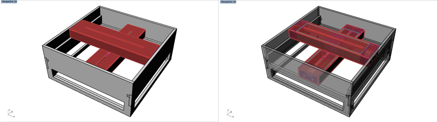
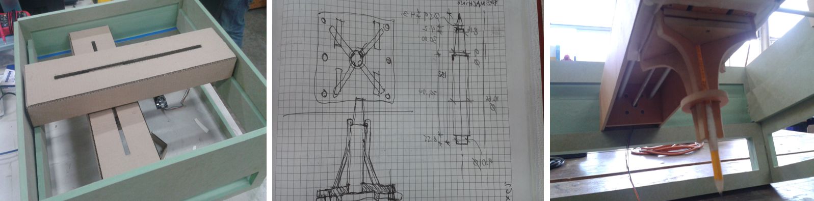
Because it was chosen the two axis x and y configuration as a first setting was discovered that the weight of the object itself in some box support will influence the correct balance among them. The last influence in the correct and firmly assembly of the cardboard flanges to ensure the moving boxes to travel without tiling. thats situation allow evaluate that it needed a guide and supporting frame for guarantee the firmly contention of first axis and the zero friction on second axis sliding. With this frame we needed to define a goal functional to use the new cnc machine, that we desired was simply and usefull: a free pen to plot plans and designs. To draw with a common pencil we need an correct distance from between movil axis and the draw canvas, and a firmly and easy pen trapping system.
The second attempt in the armed take conclussión in a possible original machine simplify that allow to do it with a fewer parts and with best firmness between sliding boxes. In the same way the revision of the original material as cardboard vs plywood, where this last one allows ensured kerf's unions vs uncertained card board folding specially talking about commented tilting. Additionally to the guide boxes the pen support was improved too; was added a kerf and skrewable base platform and a flexible ends with a final graduable fixing ring to ensure verticality.
The final product it was revealed. You can see too.
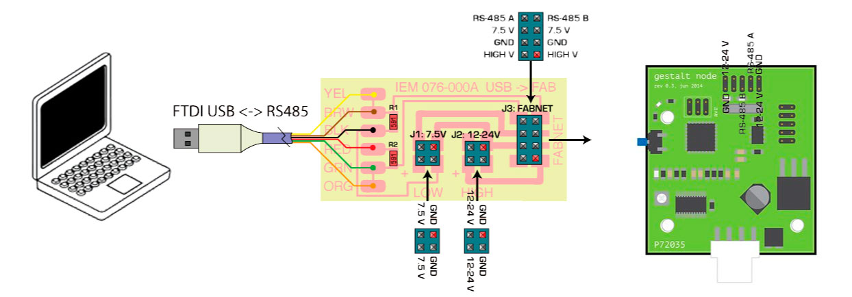
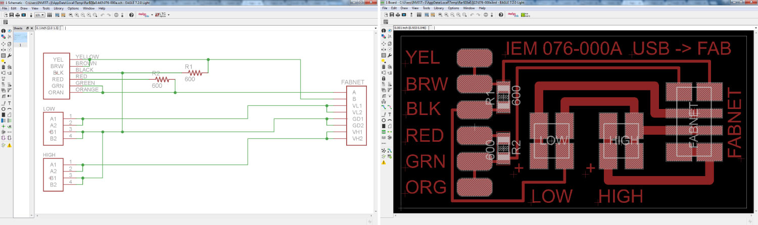
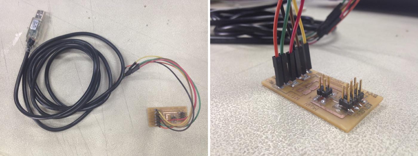
We start by downloading the eagle files to make the FABNET. The FabNet is a multi-drop network, meaning that multiple modules (a.k.a. nodes) share a single set of communication wires. Signaling is differential based on the RS-485 specification. Each node is assigned a four-byte IP address which uniquely identifies it over the network. To make the board we need the following materials:
(1) Eight pin connector, (1) Four pin connector, 2 resistors (value 600ohm) and (1) six pin connector. We milled and soldered the boards with the files provided.

Once the FabNet was ready we follow by connecting the boards following the images provided in Shawn’s tutorial.
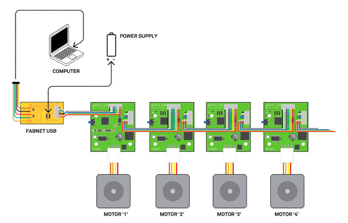
This tutorial was pretty clear in order to connect the “gestalt nodes”. For our machine we have 2 nodes. The communication between the computer and the nodes is done in series, that means that you can add as many nodes as you want following the configuration provided in the image above.
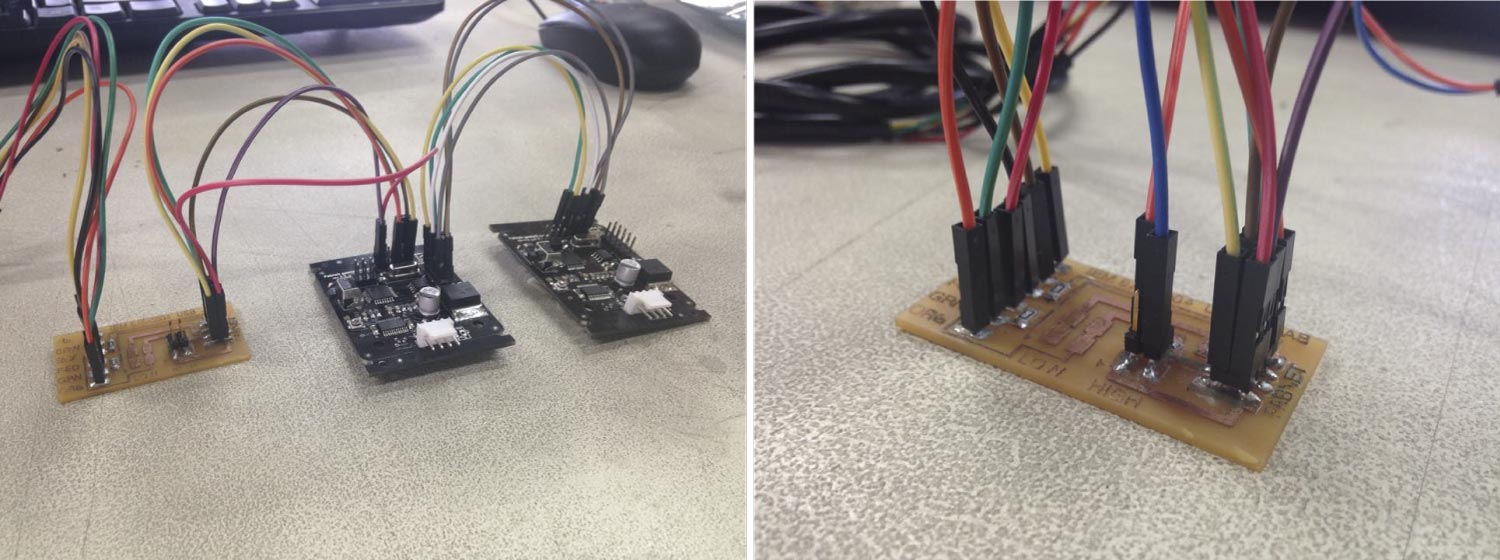
With everything connected we were ready to make the first test of the nodes.

We follow the next tutorial to program the nodes. wxGestalt is a IDE for controlling Gestalt nodes in Python. The IDE lets you configure the machine, connect to it, and create a GUI for controlling it.
Most likely wxGestalt won't have any packaged installer for a while. For the moment, you should jump in its development directly! wxGestalt uses at the moment Ilan Moyer's Gestalt, installed as a Git submodule. So, you will have to install it in this way:
Git will then dowload the Gestalt library inside the wxGestalt folder. You then have to install the dependencies for wxGestalt:
With everything installed it was time to make the first test. We modified the “xy_plotter.py” file and the next video shows the result

As you can see our machine works well, we draw on it a square and star. The star can be find code bellow.