At first, we were not clear at all about what should our machine do, and were more focused on the detalis of how to make the gestalt engine to work. After talikng over dinner in the lab, we got to a consensus about the machine being, due to time constrains, more of a Plotter.
Stages Assembly Process
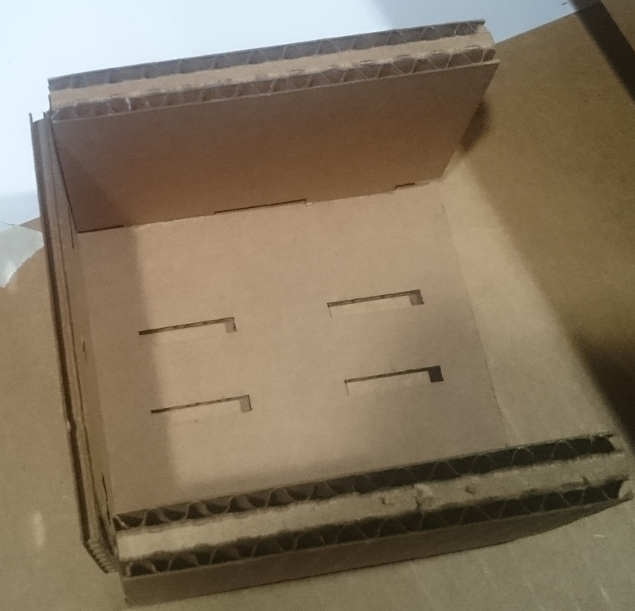
After our first attempts with Nadya's file for the uline cardboard we had available in our lab, it became clear that it needed some adjustments. Gonzalo edited the design in Corel Draw, in particular, the moving car assembly. The Before- After photos can be seen below:
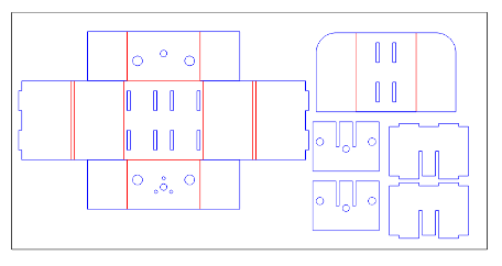
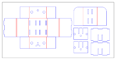
The cutting File can be found here.
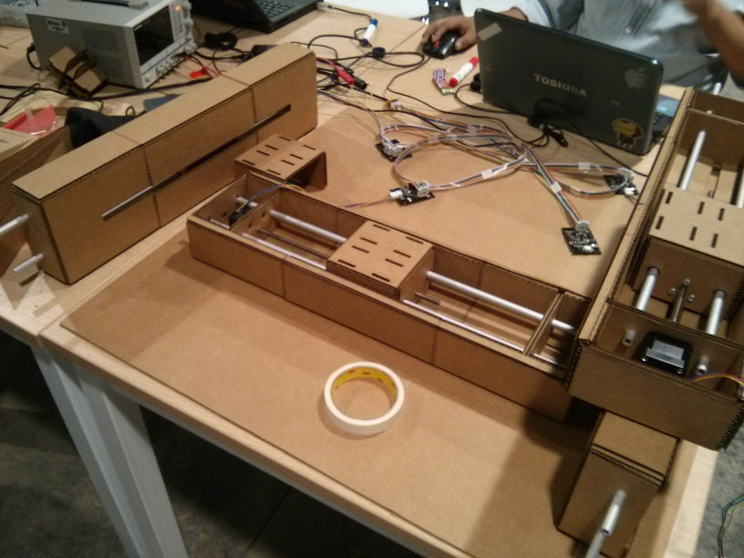
With the modified part, we cut the rest of the sections, the rest of the assembly went as expected, Mark and Arely handled most of it.
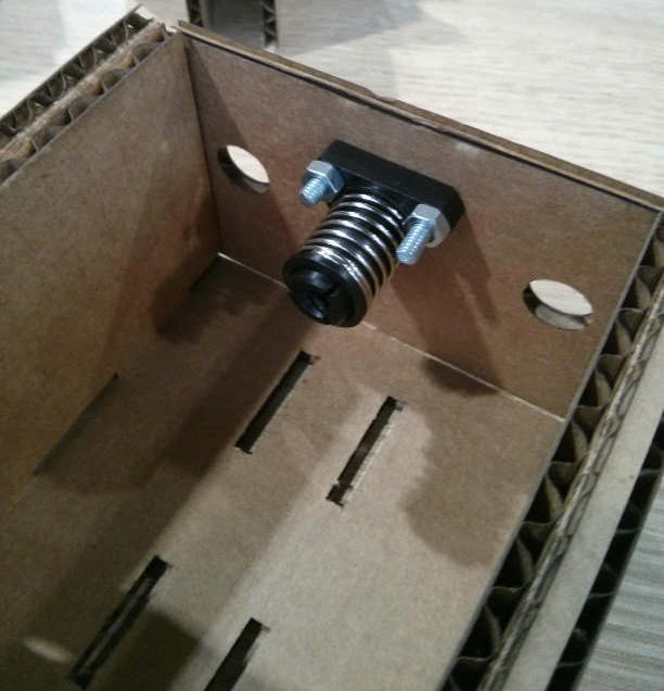
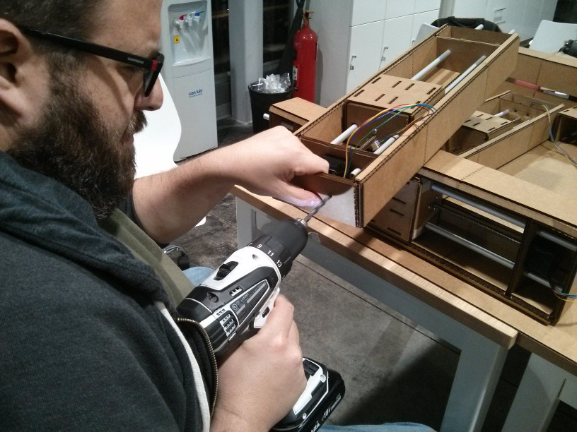
A crucial part of the Assembly was inserting the couplings for the Worm drive, pieces supplied with the nodes and motors were too big for our design, so we had to join the couplings to the "box" section of the axis drives using 3/16'' screws and securing them with nuts, we had them cut so they would not interfere with the interior parts. (see image below, left) And yet, after the first tests, the "box" of one of the modules broke, so we made another using laser-cut MDF (below, left)
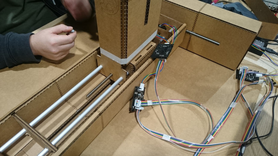
Also, we milled the interface card from the Original Fabnet files and soldered the RS-485 cable to it, Gonzalo, Cesar and Arely worked on the wiring. We did not have any problems working with the nodes and the wiring.
Testing and Setting up
With the individual stages ready, it was time to test the gestalt nodes and the motors. After we assembled the sections from the modified design, we had them ready for testing using the example scripts found on Nadya's Github.

After using the single_node.py to work, we tried to get the xy_plotter.py to work, but we could not, we tried several things, and even downloaded Ilan Moyer's Firmware and flashed it on the boards to no avail, but it seemed to be, the solution was simpler than we thought.

The breakthrough came from checking James Coleman documentation on the project:

It seemed, we simply did not notice a file test.vmp was created on first setup and we needed to delete it in order to test the other stages, after doing this it worked fine.
Afterwards, we tried to modify the code from xy_plotter.py in order to include the z-axis, but it did not seem to work until we noticed another snippet of the code:

In particular the kinematics.direct(2) in the code, when we changed it to "3", it worked fine. After doing this, we got to modify the code, adapting from the 3-axis example found in the Tutorials Section to include 4-axis so we could use all of our available stages, we would end up using 2 stages for the x-axis, and one for each y and z-axis, with the effector to be placed on the z-axis.
By then, we had already decided it would be sort of a Drawing machine, and there was left to solve which points should be fed into the python script for the machine to draw. With this objective, we made the final assembly, including an additional piece of carborard to help bond the z-axis with the y-axis stage and we used the excessive length of the aluminum rods to help the assembly, see ptohos below:
From points to pixel art
After realizing that the simplest way to plot was sending point data to the gestalt node, we decided to process a photo and convert the coordinates into movement data for the machine, Arely photoshopped it into a coarser grain photo, so Cesar could use MatLab to generate the points, duplicating one data in the python script to compensate for using two x-axis stages:
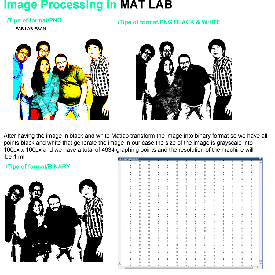
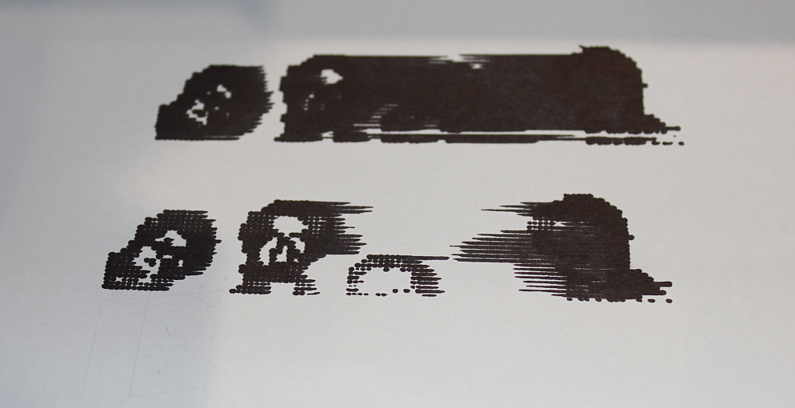
As a result of this, we got a sort of pixel-art reproduction of the image based on the points sent to it. But we still needed to get a proper effector to paint. We first tried one of the spare carboard pieces we had to insert a sharpie in it and pasted it into the machine using masking tape, it would draw a little, but we needed a better way.

To paint, we chose to use one of the Sharpies we had at the lab. Mark Designed a sort of "painting arm" to be press fit to the z-axis stage and that included a place for the sharpie. After several tries and modifications, the "arm" was firmly placed and, after some initial tries, it became clear that we needed some counterweight, in the form of some magnets.

The Files for the arm can de found in AI and DXF format
Finally, we were able to paint and draw using the machine:
And we got to register it in video:
Student Participation
All of the students in the lab worked in this assignment, it was a great opportunity to put our teamwork skills to the test, and all of them were up to the task:
- César Cruz: Helped in the mechanical assembly, electronics configuration, image processing for the pixel art drawing and path planning.
- Arely Amaut: Helped in the mechanical assembly, registering the work for further documentation shown in this page and photoshopping the image that Cesar processed.
- Mark Blanc: Helped in the mechanical assembly and integration, also designed and built the effector arm for the Sharpie.
- Gonzalo Siu: Helped in the mechanical assembly, path programming, adjusting and troubleshooting.
A "Making of" video can be found below
Another auto-generated video summary:
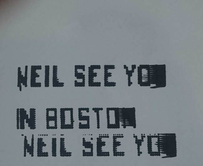
And Finally, some hope for the road, made in the machine: