14 Machine Design
Designing Network Controllable Stepper Motor Nodes
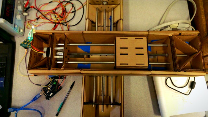
For machine building week our group decided to try and create a 2-axis machine with a stage that could track the motion of a pen drawing on a tabled. My part of the project was to design networked arduino nodes that could be individually addressed and recieve synchronization commands.
I2C and Arduino
We chose to use an I2C network for communicating between the Arduino nodes. The I2C standard includes allows for commicating with each node through unique adresses asigned to the nodes. It also provides support for a General Call address (specifically 0x00) that all nodes will respond to. The problem here is that by default the Arduino I2C library does on enable the General Call responce feature.
Enabling the General Call responce in Arduino
The ATmega has built in support for the I2C standard but it's refered to as it's Two Wire Interface in all of the documentation. In order to enable the General Call address we only need to add this one line of code in our setup function:
TWAR = 0x03;
Now is we send out a data on the I2C bus with a destination address of 0x00 all deviced on the bus will recieve the message.
Node Protocol
Each node can recieve two types of commands. Either a setup move which consists of 6 bytes that define the number of steps, step direction, and speed of the move. The second possible command is synchronized move command that all nodes revieve and initiated the start of a movement.
Here is the code for an individual node:
// Arduino based netwroked stepper motor node
#define StepPin 2
#define DirPin 5
#define Enable 8

#include <Wire.h>
int numSteps;
boolean forward;
int pulseLength;

void setup()
{
    pinMode(StepPin, OUTPUT); //STEP Output
    pinMode(DirPin, OUTPUT); //STEP Direction
    pinMode(13, OUTPUT);
    Wire.begin(1);                // join i2c bus with address #4
    Wire.onReceive(receiveEvent); // register event
    TWAR = 0x03;
    pinMode(Enable, OUTPUT); //STEP Direction
    digitalWrite(Enable, LOW);
    Serial.begin(19200);
    Serial.println("Goodnight moon!");
    }

void loop()
{   }

// function that executes whenever data is received from master
// this function is registered as an event, see setup()

void receiveEvent(int howMany)
{
    Serial.println(howMany);
    int x;
    digitalWrite(13, HIGH);   // turn the LED on (HIGH is the voltage level)
    delay(300);               // these two lines are for debugging
    if(howMany == 1)          // if we've only recieved one byte is's a general call message
    {
        x = Wire.read();
        if(x == 0)
            moveStepper();       //Check that we recieved a 0 and start the next move if we have
    }
    else if(howMany == 6)    //if 6 bytes have been recieved we're getting new movement instructions
    {
        x = Wire.read();
        numSteps = Wire.read();  // read the new instructions into their repective variables
      numSteps |= Wire.read() << 8;

      Serial.println(numSteps);
      forward = Wire.read();
      //Serial.println(forward);

      pulseLength = Wire.read();
      pulseLength |= Wire.read() << 8;
      //Serial.println(pulseLength);

     }
 }

 void moveStepper()
 {
    digitalWrite(13, HIGH);
    digitalWrite(DirPin, forward);
    for(int i = 0; i < numSteps; i++)
    {
            delay(pulseLength);
            digitalWrite(StepPin, HIGH);
            delay(pulseLength);
            digitalWrite(StepPin, LOW);
     }
    delay(pulseLength);
    digitalWrite(13, LOW);
}
Master Node
The system uses one master node that recieves the commands over the computers serial port and then sends them our along the I2C bus to all the networked nodes.
Here is the code for the master node:
#include <Wire.h>
enum state {
  address,
  numBytes,
  data0,
  data1,
  data2,
  data3,
  data4,
  tranEnd
  };
byte x = 0;
state myState = address;
int buf0, buf1, buf2,buf3,buf4, bytes, nodeaddress;

void setup()
{
    pinMode(13, OUTPUT);
    Wire.begin(); // join i2c bus (address optional for master)
    Serial.begin(19200);
    while (!Serial) {
    ; // wait for serial port to connect. Needed for Leonardo only
    }
    Serial.println("Goodnight moon!");
    digitalWrite(13, HIGH);   // turn the LED on (HIGH is the voltage level)
    delay(500);              // wait for a second
    digitalWrite(13, LOW);    // turn the LED off by making the voltage LOW
    delay(500);
}

void loop()
{
    if (Serial.available())
    {
        if(myState == address)
        {
            nodeaddress = Serial.read();
            Serial.write(20);
            Serial.write(nodeaddress);
            myState = numBytes;
        }
        else if(myState == numBytes)
        {
            bytes = Serial.read();
            Serial.write(21);
            Serial.write(bytes);
            myState = data0;
            if(bytes == 0)
            {
                Wire.beginTransmission(nodeaddress);
                Wire.write(bytes);
                Wire.endTransmission();
                myState = address;
                Serial.write(29);
            }
        }
        else if(myState == data0)
        {
            buf0 = Serial.read();
            Serial.write(22);
            Serial.write(buf0);
            myState = data1;
        }
        else if(myState == data1)
        {
            buf1 = Serial.read();
            Serial.write(23);
            Serial.write(buf1);
            myState = data2;
        }
        else if(myState == data2)
        {
            buf2 = Serial.read();
            Serial.write(24);
            Serial.write(buf2);
            myState = data3;
        }
        else if(myState == data3)
        {
            buf3 = Serial.read();
            Serial.write(25);
            Serial.write(buf3);
            myState = data4;
        }
        else if(myState == data4)
        {
            buf4 = Serial.read();
            Serial.write(26);
            Serial.write(buf4);
            Wire.beginTransmission(nodeaddress);
            byte bArray[6] = {bytes,buf0,buf1,buf2,buf3,buf4};
            Wire.write(bArray,6);
            Wire.endTransmission();
            myState = address;
        }
    }
}
Processing Based Virtual Machine Driver
In order to abstract the conrol nodes into virtual software objects I created a StepperMotor class that would be used to control each device.
Here is the code for that class:
class StepperMotor {
    public int address;
    public StepperMove nextMove;
    public  int direction;
    public  int numberOfSteps;
    public  int time;
    // The Constructor is defined with arguments.
    StepperMotor(int myAddress) {
        address = myAddress;
    }
    void moveAll() {
        myPort.write(0); //Send General Call address
        myPort.write(0); //Send a move instuction (0)
      }
    void sendNextMove(int direction, int numberOfSteps, int time){
        myPort.write(this.address);
        myPort.write(5);
        myPort.write(numberOfSteps & 0x00FF);
        myPort.write(numberOfSteps >> 8);
        myPort.write(direction);
        myPort.write(time & 0x00FF);
        myPort.write(time >> 8);
    }
}
Video of the machine tracing out a path drawn by a pen tablet:
Next Steps
Our system worked but the motion was not very smooth as we were puasing between each synchronized move. Adding the ability to queue up multiple instructions in each node and adding feedback from the nodes would be a great next step.