09 Input Devices
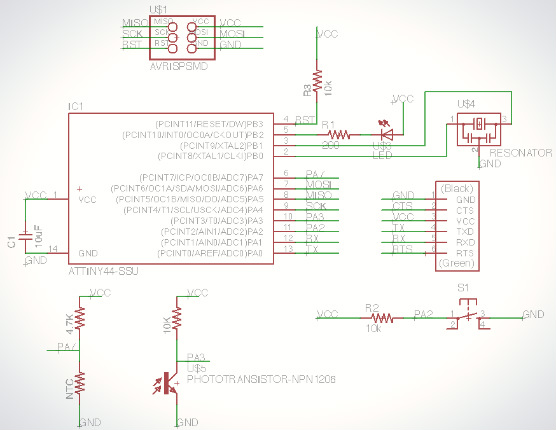
For this week I created another version of my ATTiny based microcontroller board and added a temperature sensor and light sensor. I also experimented with using a two sided board design to make routing the board much easier. Below is the schematic design with the added components:
- 365-1157-1-ND Phototransistor
- 235-1109-1-ND Thermistor (NTC 10kohm)
Both of which are simple sensors that change resistance based on their designed input variable(light or temperature). By placing them into a voltage divider network we can easy measure their input level by using the analog read function of our processor.
 To make a double layer board I decided to use the bottom layer as just be a complete ground plane I didn't need to actually cut it. I used the Autorouters "Select" tool to select the GND signal and set the layer cost of the Top layer to 99 and the cost of Vias to 50. This cause it to route the signal on the back plane for most of the route. I also enlarged the DRC minimum via size so that I could drill the vias with a 1/32 in bit.
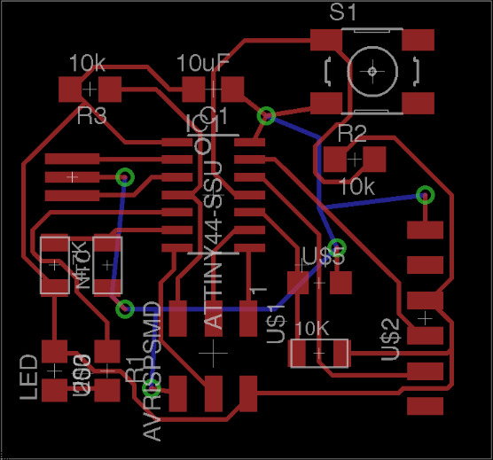
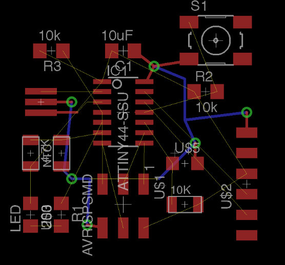 After the Ground plane was routed I set the Autorouter back to routing only on the top layer and routed the rest of the board.
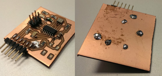
 After milling the board I just had to solder in jumpers through the board at each via hole.
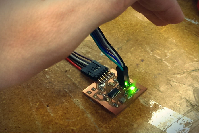
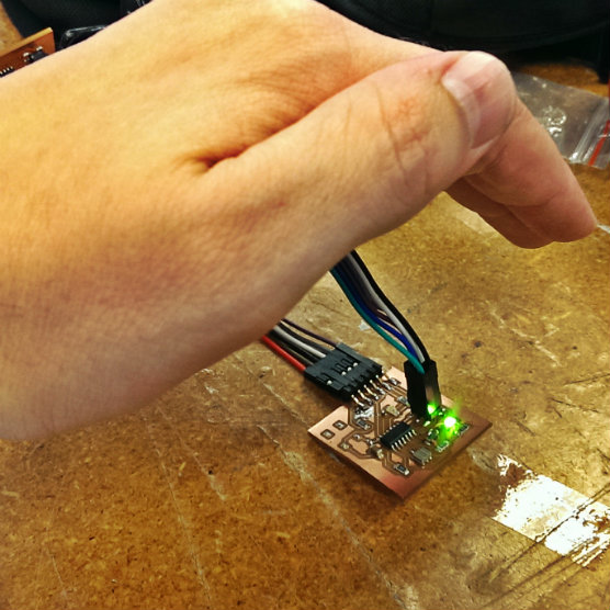
 I then programmed the board to light up the LED whenever the light level dropped below ambient light levels.
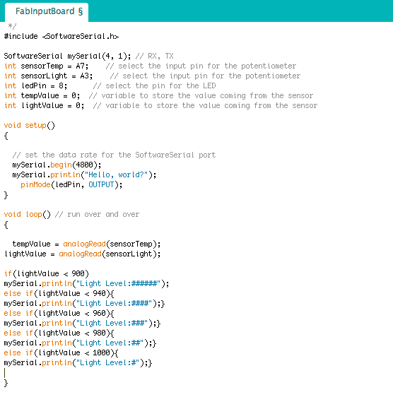
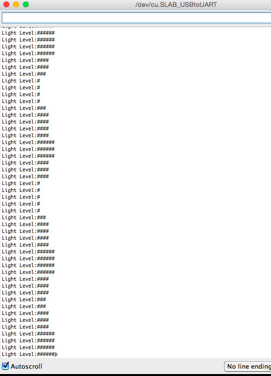
 Next I very roughly visualized the light level by mapping the light level to some serial port ASCII art for a real time graph.
Code provided below:
#include <SoftwareSerial.h>
SoftwareSerial mySerial(0, 1); // RX, TX
int sensorTemp = A7;    // select the input pin for the potentiometer
int sensorLight = A3;    // select the input pin for the potentiometer
int ledPin = 8;      // select the pin for the LED
int tempValue = 0;  // variable to store the value coming from the  sensor
int lightValue = 0;  // variable to store the value coming from the sensor
char val; // Data received from the serial port

void setup()
{
      // set the data rate for the SoftwareSerial port
      mySerial.begin(9600);
      mySerial.println("Hello, world?");
      pinMode(ledPin, OUTPUT);
}

void loop() // run over and over
{
       lightValue = analogRead(sensorLight);
       tempValue = analogRead(sensorTemp);
   if(lightValue < 900)
     mySerial.println("Light Level:#####");
   else if(lightValue < 940){
    mySerial.println("Light Level:####");}
   else if(lightValue < 960){
    mySerial.println("Light Level:###");}
   else if(lightValue < 980){
    mySerial.println("Light Level:##");}
    else if(lightValue < 1000){
     mySerial.println("Light Level:#");}
   }
 Here is the result when I wave my hand over the board:
Design Files
Code above.
Eagle CAD files can be downloaded here.