05 Electronics Design
Motivation
For my final project I need a solar colection system that can charge a battery in bright indoor condition. So for this weeks assignment I chose to design a circuit and subsequent board based on the TI BQ2505 Ultra Low Power Energy Harvester Chip and a 5V boost converter chip to so that this version can at least charge a cell phone.
Circuit Design
The first step was following the reference designs from the data sheets and creating a schematic in eagle. The trickiest part here was choosing all the resistor values to set the battery charge values and hyterysis points.

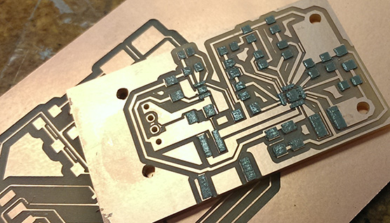
Board Layout
This took some time and itterations with trying to mill the boards. The only packages available for the two chips where no lead packages that requred traces that only the .010 inch mill bit could mill out. To increase the chance that traces would survive milling I had to create copper pour sections that widened as soon as they left the chips pad areas.

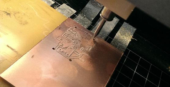
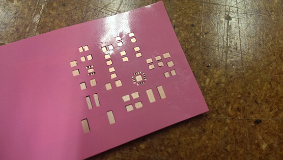
Milling
I lost a few .010 bits before I realized the set screw was too stiped and no longer tightning far enough
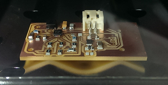
Reflow Soldering
This actually went pretty smooth. surface tention managed to seperate the almost all the solder between the smallent surace mount pins though a few had the be reflowed after with a fine tip soldering iron in order to get them to seperate.
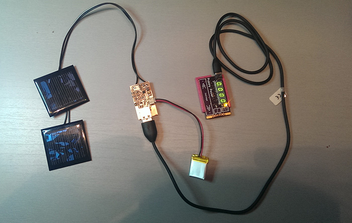
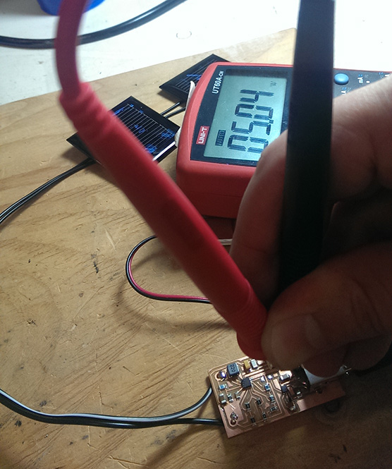
It worked!!!!
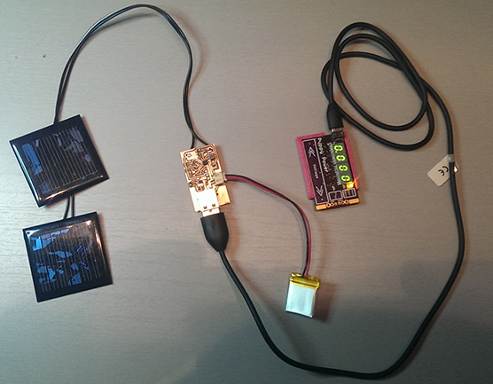
Even under desk lamp lighting the circuit was able to power up and provide a charge current for the Li-po battery. The boost converter was also able to start up and provide a 5V bus.
 Here's is the final circuit powering up another small board I designed that happens to run off of 5V. And in bright light conditions it was able to charge my phone and the backup battery at the same time.
Design Files
All the Eagle CAD design files can be downloaded here.