Week 8: Computer-Controlled Machining
3.18.2015 - 3.24.2015
Lecture Notes:
Homework:
- Mill a large project
Resources:
- Fab
Academy Handbook
- Vectric V Carve Pro: http://www.vectric.com/products/vcarve-pro.htm
- Shopbot
Feed and Speed Chart
Files:
Acknowledgements:
Many thanks to Andrew, Brandi, Nathan, and Igor for their
assistance during assembly.
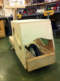
Project:
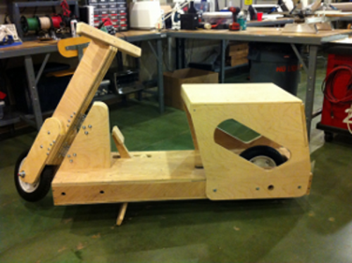
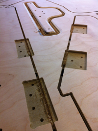
Plywood comprised the scooter's frame, gate hinges comprised the steering column, and wheelbarrow wheels and tires were used for wheels. Hex bolts, threaded rod, wood screws, lag screws, tee nuts, and hinges comprised the remaining hardware.
Design:
I designed glued and fastened butt and dado joints along with
laminated beams for the scooter's frame rather than elaborate
finger joints, snapping/locking joints, or living hinges.
Flush edges, pre-drilled holes, counter bored holes, and slots
facilitated aligning and assembling the parts.
Factors that influenced the scale of the scooter
included: 1) the scale and position of the rider, 2)
plywood sheet dimensions, 3) engine dimensions, and 4) wheel
dimensions. While I did not intend to motorize this
particular project, I did allow space for a rear wheel sprocket
and chain transmission within the scooter's design.
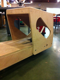
I designed the scooter to have modular sub-assemblies that
could be independently redesigned and revised without affecting
the remainder of the frame. The scooter's five
sub-assemblies: 1) platform, 2) seat, 3) steering column,
4) steering post, 5) handle bars were joined with bolted
connections.
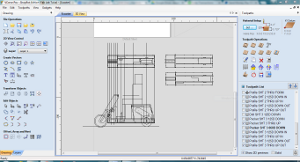
Scooter parts were designed for 0.719 inch (18.25 mm) 5-ply
poplar plywood and drawn and tool pathed using VCarve Pro 7.0.
 |
 |
Consideration was given to anticipated principal loads,
ply orientation within parts, sub assembly modularity, fastener
access, driver ergonomics, power plant and transmission
elements, and part nesting. The scooter was designed
around 95th percentile adult male body dimensions.
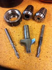
| Property |
Down-Cutting 0.25 inch End Mill |
Plungeable Roundover End Mill |
Up-Cutting 0.25 inch End Mill |
| Dimensions |
0.25 in (6.4mm) |
0.375 in (9.5mm) minor 1.375 in (34.9mm) major |
0.25 in (6.4mm) |
| Flutes |
2 |
2 |
2 |
| LOC |
2 in (50.8mm) |
0.75 in (19.1mm) |
2 in (50.8mm) |
| Pass Depth (Z) | 0.25 in (6.4mm) |
0.375 in (9.5 mm) |
0.25 in (6.4mm) |
| Step Over
(XY) |
0.125 in
(3.2mm) |
0.25 in (6.4 mm) |
0.125 in (3.2mm) |
| Spindle Speed | 12K RPM |
10K RPM |
12K RPM |
| Feed Rate
(XY) |
3 in/s (76.2 mm/s) |
2 in/s (50.8 mm/s) |
3 in/s (76.2 mm/s) |
| Plunge Rate
(Z) |
1 in/s (25.4 mm/s) |
1 in/s (25.4 mm/s) |
1 in/s (25.4 mm/s) |
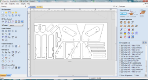
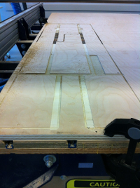
Three tools, eight cut files, twenty nine separate tool paths,
and approximately 2 1/3 sheets of plywood were required to
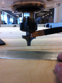
fabricate the scooter frame. All toolpaths (drilling,
pocketing, and profiling) were initiated with the down-cutting
end mill and cut to a shallow depth. All through-sheet
tool paths were completed with an up-cutting end mill. By
using the two tools in this sequence, the part edges were smooth
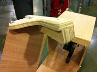
and splinter-free. Parts profiled with the round over end
mill (seat and handle bars) were milled without tabs and held in
place with wood screws.
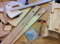
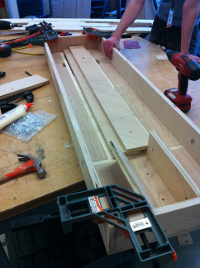
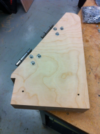
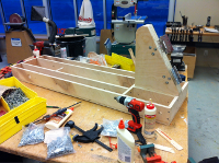
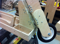
Milling & Assembly:
The following sequence of images illustrate the Scooter's
milling and assembly steps.
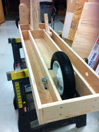
The scooter parts was assembled in the following order:
- Platform (lower sheet, sides (with tee nuts) and internal
webs, rear wheel, brake pedal, upper sheet)
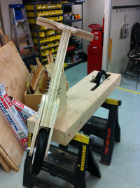
- Steering Post
- Steering Column
- Seat
- Handle bars
- Kickstand (optional)
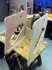
The steering post and column sub assemblies should ideally be
constructed simultaneously to permit the insertion of both ends
of the hinges into their respective pockets and shimmed with
washers where necessary.
 |
 |
 |
 |
 |
 |
 |
 |
 |
 |
 |
 |
 |
 |
 |