Week 7: Embedded Programming
3.11.2015 - 3.17.2015
Lecture Notes:
Homework:
- Read a micro-controller data sheet
- Program the modified echo hello-world board (week 6)
to do something
Resources:
- Fab
Academy Handbook
- http://academy.cba.mit.edu/classes/embedded_programming/index.html#echo
- http://academy.cba.mit.edu/classes/electronics_production/index.html
- http://academy.cba.mit.edu/content/tutorials/akf/programming_FabISP.html#ubuntu
- http://academy.cba.mit.edu/content/tutorials/akf/hello_echo_c.html
- http://academy.cba.mit.edu/content/tutorials/akf/embedded_programming_arduinoIDE.html
- http://arduino.cc/en/Main/Software
- http://playground.arduino.cc/learning/linux
- http://playground.arduino.cc/Linux/Ubuntu
- http://www.atmel.com/devices/attiny44.aspx
- http://www.atmel.com/images/doc0943.pdf
Files:
- Arduino Sketch
Acknowledgements:
Many thanks to Andrew Harmon for his guidance on this project.
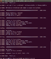
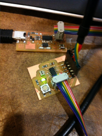
Fab ISP Programming:
The AS220 Fab Academy tutorials were very useful to setup the
ISP board. The essential steps included: 1)
downloading the firmware, 2) programming the ISP and setting the
fuses (make clean, make hex, make fuse, make program), 3)
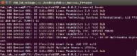
verifying the ISP is working, and 4) desoldering components from
the ISP board. I ran into a few errors while using these
instructions but they were ultimately the result of some missing
sudo commands within the make fuse and make program steps.
 |
 |
 |
ATMEL ATTiny44 Datasheet:
Useful information from the ATTiny44
datasheet included:
The Overview (pp4) of the ATTiny 44 describes its 4
byte In-System Programmable Flash, 256 bytes EEPROM, 256 bytes
SRAM, 12 general purpose I/O lines, an 8-bit Timer Counter and
other specifications.
Memories (pp15) section describes the ISP
re-programmable Flash program memory, SRAM, and EEPROM
memories. Flash memory can undergo 10K write/erase
cycles.
Serial Programming (pp163) is controlled through
the MOSI (Master Out - Slave In, pin PA 6) input (ISP to AVR)
and MISO (Master In - Slave Out, pin PA5) output (AVR to
ISP). Both EEPROM (electrically erasable programmable
read-only memory) and Flash (power independent) memory arrays
can be programmed while RESET (pin ) is pulled to ground.
DC Characteristics (pp 175) for the chip include maximum
supply currents between 0.8-9 mA (active) and 0.4-3.5mA (idle)
depending on the frequency 1-8MHz and voltage 2-5V.
Speed (4-10MHz) is a function of Vcc (1.8-5.5V) and varies
linearly from 1.8-2.7V. Typical Characteristic section
(pp 185) describes other current vs frequency relationships.
Clock Characteristics (pp 176, 206) describe how the
internal oscillator's frequency is a function of temperature and
voltage and can be calibrated manually. Clock accuracy can
vary between +1-10% depending on the calibration method.
The ATMEL AVR910 document here describes
In-System Programming with plans for an ISP.
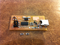
Hello.ftdi.44.echo Arduino IDE Programming:
The Hello.ftdi.44.echo board programming also followed the
AS220 Fab Academy tutorials. The essential steps included
1) installing Arduino IDE sotware, ATtiny board files and FTDI
drivers, 2) configuring the ATtiny and selecting the programmer,
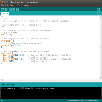
3) burning the bootloader, 4) writing, modifying, saving and
uploading an Arduino sketch to the Echo Hello World board.
Testing:
To date I have been unable to have the hello.echo.44 board successfully communicate or "echo" through the serial monitor window within the Arduino software despite investigating different serial ports and options with the serial monitor. Text sent to the board does not return a response.
 |
 |