Week 16: Machine Design
5.14.2015 - 5.20.2015
Lecture Notes:
Homework:
- As a group, within two weeks, make a machine including the end effector from the plans provided. Operate the machine manually. Document the groups project and individual contributions.
Resources:
- Fab
Academy Handbook
- http://mtm.cba.mit.edu/
- http://mtm.cba.mit.edu/machines/science/
- http://monograph.io/james/m-mtm
- http://mtm.cba.mit.edu/machines/science/doc/scienceBOM.pdf
Files:
Acknowledgements:
Thanks to Jean-Luc Pierite for his collaboration on this project.Project:
As I am working alone within my local lab during Fab Academy 2015, I was partnered through my instructor with Jean-Luc Pierite who is located at the South End Technology Center in Boston on this project. My responsibilities for this group project would include the design of the end effector while Jean-Luc's would include the gestalt programming.Stage Construction:
I began this project by constructing a single linear stage from
the mMTM website here
and the hardware supplied through the Fab Academy program as
part of this weekly assignment. These plans were
designed for a larger laser cutter than our Epilog Mini 24 40W
laser cutter and as I did not see the link to the smaller cut
files here,
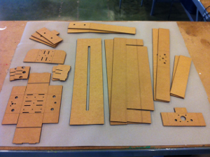
I spent some time dissecting these DXF files into smaller pieces
and saving them into PDF-formatted files.
 |
 |
 |
 |
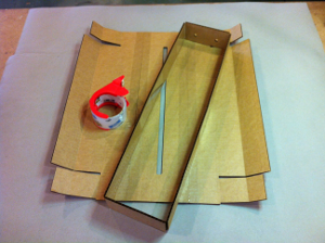
The cardboard components were designed for 0.15 inch (3.8 mm)
material. I found folding and layering the structure and
the alignment and insertion of the mortise and tenon joints to
be very sensitive to material thickness and tenons many times
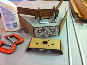
crushed (corrugation direction played some part). Keeping
the long folded surfaces that made up the edges of the housing
flat and square required some additional clamping and
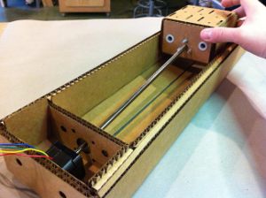
gluing. The carriage proved generally rigid enough to not
require using its internal structure and removing that structure
allowed me to install fasteners to hold the end effector
later. The side of the carriage nearest the stepper motor
was flexible enough however to question the effectiveness of the
anti-backlash nut.
I also had to substitute the M3 x 8 screws that came with the
supplied stage hardware with M3 x 12 screws I had in the lab in
order to mount the stepper motor through two layers of cardboard
without significantly crushing the cardboard.
Epilog Mini 24 40W laser cutter settings used to cut and score
the cardboard stage housing are shown below:
| Type |
Speed |
Power |
Freq |
| Scoring |
100 % |
30 % |
5KHz |
| Cutting |
60% |
100% |
5KHz |
End Effector Design:
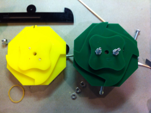
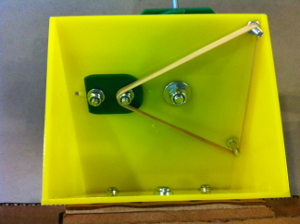
Rather than design a single-purpose end effector, I designed a four-position tool changer that would increase the versatility and usefulness of a single stage. I wanted to make a simple and inexpensive tool changing mechanism that would 1) suit the simple construction of the cardboard stage, 2) not require any additional circuitry or electronic controls, and 3) could be used with only a single stage.The tool changer utilized the stage's existing stepper motor and linear forward and reverse motion to mechanically index up to four tools while sacrificing a portion of its range (~70mm) to the tool changing operation. A ratchet and pawl was used to rotate a the tools mounted to a common skewed faceplate. A four-lobed cam and spring loaded cam follower were used to retain the position of the tools once rotated. The skewed orientation faceplate presented just on tool at a time to the workpiece.
End Effector Fabrication:
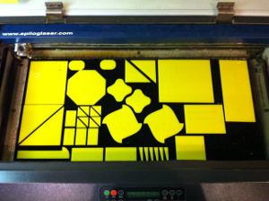
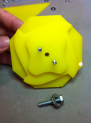
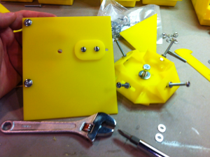
I used Inkscape to layout the tool changer's parts and laser cut them from a single 12in x 24 in x 0.110 in (305mm x 610mm x 2.79 mm) cast acrylic sheet. 40W CO2 laser vector cutting settings are as follows: Speed 10%, Power 100%, Frequency 5KHz.Parts were designed to be bonded into sub-assemblies using acrylic solvent and the sub-assemblies fastened using #8 screws, hex nuts, and nylon lock nuts. Screws were used to temporarily keep the cam, ratchet, and faceplate concentric and clamped during the bonding step.
 |
 |
 |
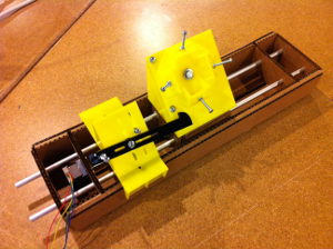 |
Machine screws are used to represent tools above. The additional slotted pawl was used to experiment with different lengths and angles.
End Effector Testing and Revision:
During and after fabricating the first tool changer I tested the fit of mating parts, behavior of the cam and cam follower, length and position of the pawl, and importantly the interaction of the pawl and ratchet manually. Parts were modified to remove interferences discovered during assembly.The original pawl and ratchet did not remain engaged sufficiently long enough to rotate the cam a quarter turn and required redesigning the ratchet. The rake of the pawl and ratchet teeth was increased in order to delay their disengagement and rotate the cam past each lobe. Redesigning the pawl and ratchet teeth was used as an opportunity to perform other modifications including: enlarging of the shared cam, ratchet, and faceplate axle hole, shortening of the cam follower retainer, shortening the tool mount brackets, realigning the registration holes within the cam by 45 degrees, adding an additional cam layer, and adding an additional pawl shim.
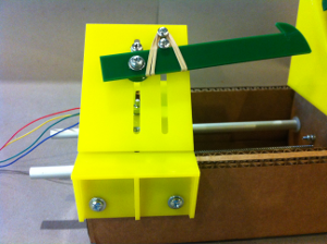
Following redesigning and reassembling portions of the tool changer, I spent considerable time calibrating it. Tool changer performance was influenced by the force applied by the rubber band(s), friction of the cam and cam follower against the carriage bracket, the tightness of the nylon lock nuts used to fasten components together, and the height and angle of the pawl. Deflection of the pawl (a single acrylic layer thick) and the deflection of the cardboard carriage and cardboard stage housing beneath the pawl and carriage brackets also affected performance.
 |
 |
 |
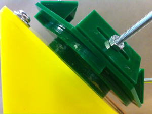 |
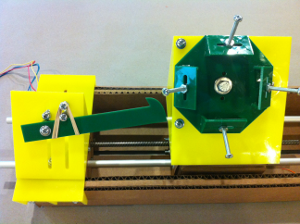
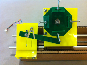
I mounted the pawl assembly over the stepper motor end of the stage by pinning it with machine screws and put it through several manual cycles with my hands. Important distances as measured from the pawl bracket's leading edge to the leading edge of the cardboard carriage (lead screw nut end) that would influence the range of the stage are as follows:
4. 9 mm - Minimum distance between carriage and stepper motor partition; acrylic brackets make contact
 |
 |
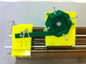 |
These approximate distances. The stage would loose at least 70mm of its range in the current design or potentially more since the pawl assembly can be mounted anywhere along the length of the lead screw. Carriage travel for tool changing could be limited with micro switches as well.