Week 13: Networking and Communications
4.29.2015 - 5.5.2015
Lecture Notes:
Homework:
- Design and build a wired and/or wireless network connecting
at least two processors
Resources:
- Fab Academy Handbook
- Atmel
ATtiny 45 Datasheet
- hello.bus.45.node trace,
interior
- hello.bus.45.bridge trace,
interior
Files:
Acknowledgements:
Thanks to Andrew Harmon for his guidance on this project.Project:
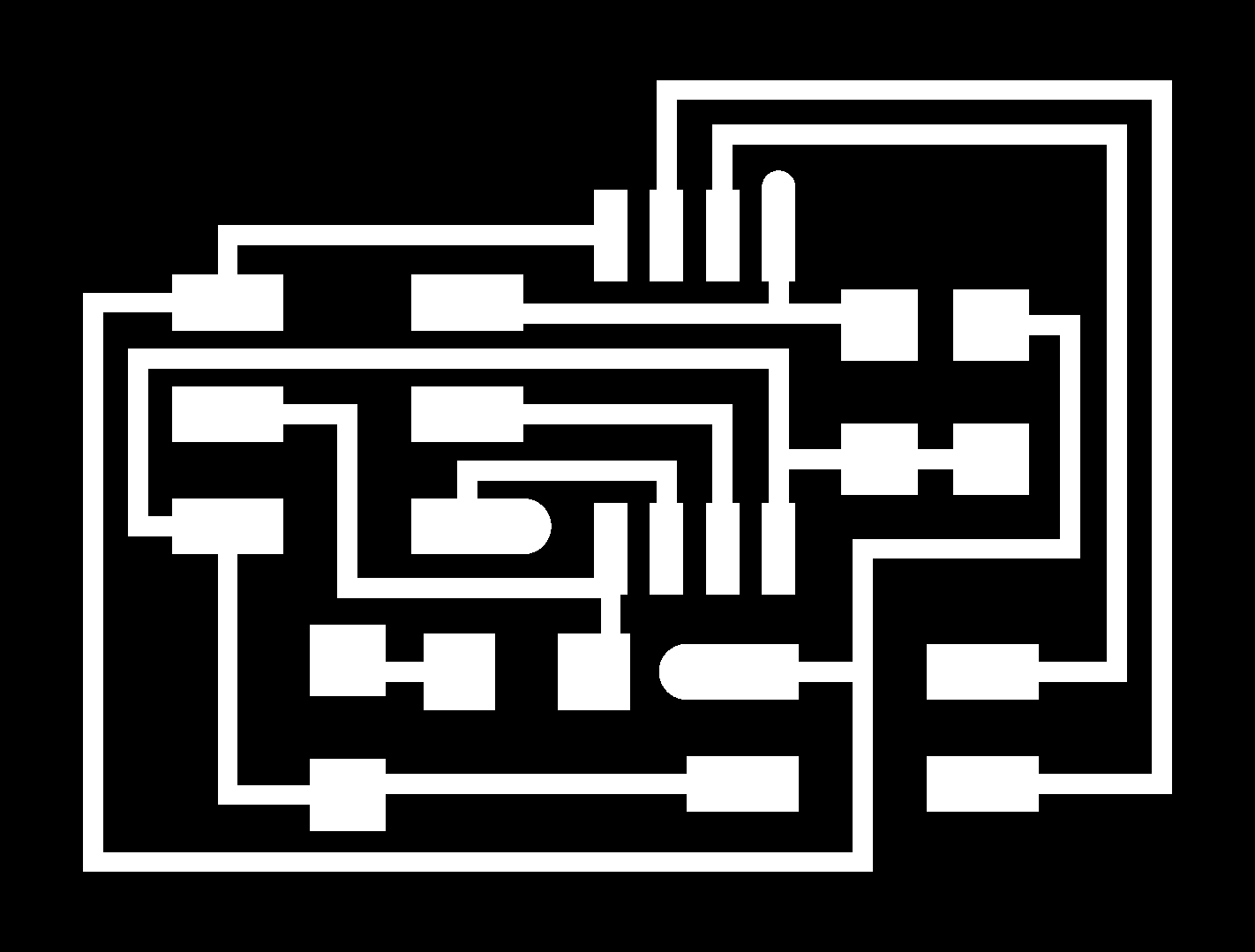
I began this assignment by fabricating a two node plus bridge asynchronous serial network according to the hello.bus.45 example contained here.For experience, I redrew these boards in Eagle and milled them using the Roland MDX-20. I ultimately milled more than three boards after spending sometime troubleshooting issues including bridged traces and damaged traces due to removing the FTDI socket.
Attempting to communicate with the boards using Arduino IDE revealed errors that pointed to the bridged traces. Bridged traces were separated with a utility knife and repairs were checked with a multimeter. Following redesigning these boards I began manually rather that auto-routing my traces and used a FTDI headers that lay flat to the surface of the board.
Once the boards' fabrication issues were corrected, I attempted to communicate with the network board over serial communication. I used a simple code to have the bridge return a message to the Arduino serial monitor. Despite investigating input voltage, different settings within the Arduino Tools menu, and baud rates the output returned to the serial monitor was not recognizable. As an experiment, the micro-processor was heated with an air gun while running the Arduino serial sketch. The additional heat led the ATTiny 45 to return the correct output to serial monitor without errors. This result was immediate and repeatable. The ATTiny's internal 8MHz oscillator's temperature dependency is described within the datasheet (pp 193).
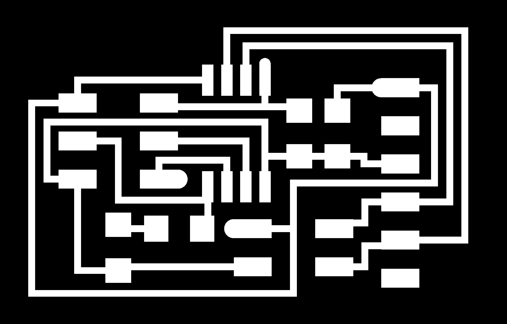
I opted to fabricate new boards based on the ATtiny 44 chip which offered additional input pins that would accommodate an external 20 MHz resonator instead of the using an internal clock as with the ATtiny 45. I designed a single board that would serve both roles as a bridge and a node.