Week 12: Composites
4.15.2015 - 4.21.2015
Lecture Notes:
Homework:
- Design and fabricate a 3D mold and use it to form a fiber
composite part
Resources:
Files:
Acknowledgements:
Many thanks to Andrew Harmon for his assistance during assembly of this project.Project:
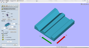
For this project I designed a one-part female MDF mold for laying up, bagging, and forming composite channels and angles.Design:
Using AutoDesk Inventor, I designed a reusable female mold surface for that included parallel right angle and rectangular channel cavities. Interior and exterior mold cavity corners were rounded.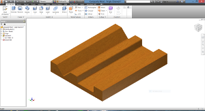 |
 |
 |
 |
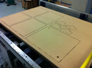
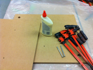
Using VCarve Pro 7.0, I created a separate 2D file to cut the parts of the laminated MDF block.
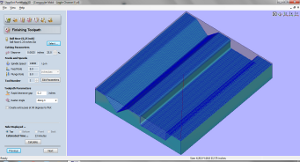
Toolpathing:
The mold STL file was tool-pathed using PartWorks 3D.
Roughing and finishing passes were oriented along the length of
the mold (x-axis) to minimize roughened edges around abrupt
changes in surface geometry particularly the vertical sides of
the channel. Both roughing and finishing passes used the
same 0.25 inch (6.35 mm) ball nose end mill for
convenience. Finishing passes were spaced more closely
than roughing passes.
 |
 |
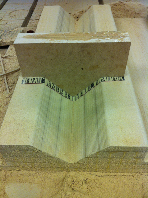
The model was recessed below the upper surface of the material
which, due to the thickness of that margin and the pass interval
setting of the tool, led to complications during milling.
Decreasing the pass interval or the depth of the model beneath
the surface of the material would address the excess margin.
Spindle speeds and milling feed rates are listed below:
| Property |
2D Milling |
3D Milling |
| Dimensions / Type |
0.25 in / Square (6.4mm) |
0.25 in / Ball (6.4mm) |
| Flutes |
2 |
2 |
| LOC |
1.5 in (50.8mm) |
1.5 in (50.8mm) |
| Pass Depth (Z) | 0.25 in (6.4mm) |
0.25 in (6.4mm) |
| Step Over
(XY) |
0.125 in (3.2mm) |
0.125 in
Rough (3.2mm) 0.0625 in Finish (1.6mm) |
| Spindle Speed | 12K RPM |
12K RPM |
| Feed Rate
(XY) |
2.5 in/s (63.5 mm/s) |
2.5 in/s (63.5 mm/s) |
| Plunge Rate
(Z) |
1 in/s (25.4 mm/s) |
1 in/s (25.4 mm/s) |
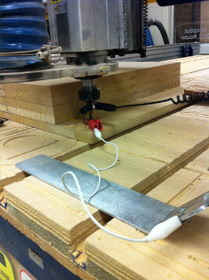
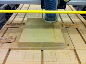
Milling:
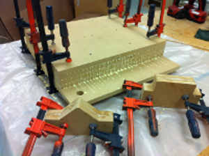
The laminated MDF block used for the composite mold was located
on the Shopbot's machine bed using an SBP file constructed by
one of Fab Lab Tulsa's members, Dana Swift. By reusing the
z zeroing plate and clamp circuit, the file positions a tool in
the center of a conductive ring (a copper cap in this case) by
alternatively moving in the x and y directions and stopping it
when it makes contact with the ring's edge. Alternatively
measuring within copper caps in two locations on the MDF block
allowed me to align the block's material axes parallel to the
Shopbot's machine axes.
 |
 |
 |
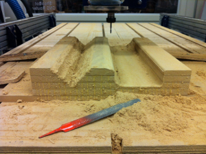 |
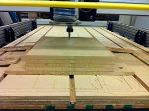
The Shopbot was stopped regularly to rasp the inner corner of
the channel cavity during the finishing pass. The spindle
nut made contact with the corner of the channel mold due to
extra margin not removed during the roughing tool path and
insufficient end mill cutting length to clear the additional
height. The Shopbot was operated with a dust collector
running but without the dust shoe for clearance reasons.
An in-room air filter was also used during the milling process.
 |
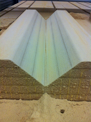 |
I used the custom sanding block that conformed to the inner
surface of the angle mold to uniformly remove tool marks and
preserve the mold's cross-sectional surfaces and angles.
Lay Up & Bagging:
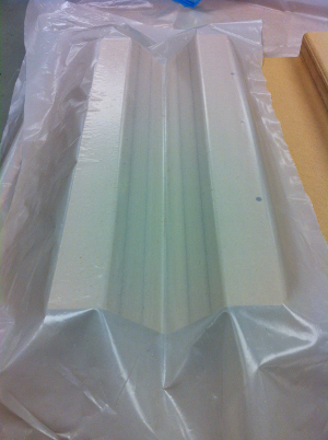
Following sanding, the MDF mold was lined with 0.004 inch (0.1
mm) thick polyethylene film. Aerosol adhesive was used to
bond the lower side of the film to the mold while mold release
was applied to the film's upper surface ahead of applying the
burlap.
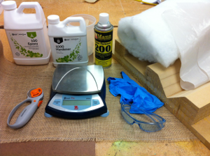
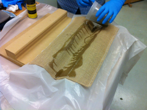
Over-sized burlap plys were cut beforehand using a rotary
cutting wheel which minimized edge fraying. I used
approximately 300g of Super Sap 100 epoxy resin, mixed by mass
in a 100:48 epoxy to hardener ratio, to lay up 4 burlap
plys.
 |
 |
 |
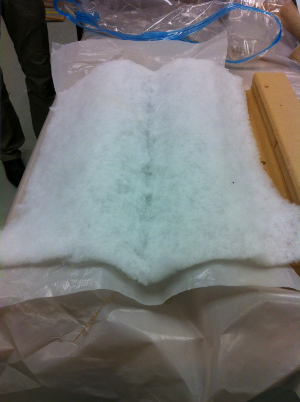 |
Excess burlap was cut away with scissors prior to applying a
second perforated 0.004 inch thick polyethylene film with mold
release. The perforations were made by hand with rasps and
awls and allowed the trapped air and excess resin to migrate
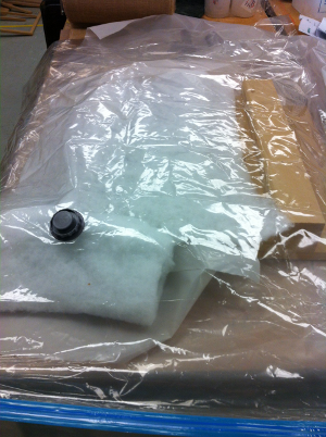
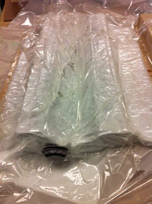
through and out of the laminate. Polyester batting was cut
and laid on top of the perforated film, the entire mold assembly
place in a vacuum seal bag and additional batting placed beneath
the vacuum port.
The vacuum used to seal the bag permitted an external pressure
of approximately 2.5 psi (17 kPa) to be applied over the surface
of the mold . The bag was wrinkled above the laminate
prior to pulling a vacuum to allow it to conform to the mold's
surface. I would round the corners of future molds to
minimize the risk of sharp corners puncturing the bag under
vacuum.
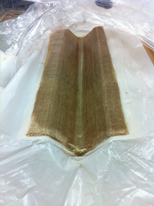
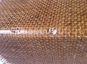
Demolding and Finishing:
The composite angle was left to cure for 9 hours before
separating it from the mold. Its outer surface showed very
few voids and generally no dry areas within the angle
flanges. Excess resin did pool in the angle's corner due
to the orientation of the mold. Additional perforations to
upper release film, more slack in the vacuum bag, and less
applied resin all could help reduce resin pooling.
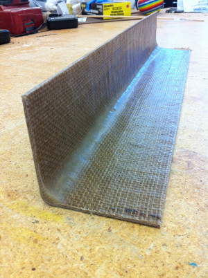
Irregular edges and excess material were trimmed using a band saw.
 |
 |
 |
 |
 |
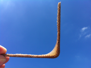 |
Versatile cross-sections such as angles and channels can serve
as the building blocks to larger load-bearing composite
structures such as trusses. Cut to different lengths, the
angle can serve as a beam or a bracket.