Week 10: Input Devices
4.8.2015 - 4.14.2015
Lecture Notes:
Homework:
- Design a micro-controller board with a sensor and measure
the sensor's output
Resources:
- Fab
Academy Handbook
- Fab Modules
- Adafruit
Eagle Component Package Tutorial
- SparkFun Eagle SMD Footprint Tutorial
- Instructable
Eagle Custom Library Part Tutorial
- Arduino Language Reference
- Atmel
ATtiny 45 Datasheet
- Vacuum
Sensor, Vacuum
Sensor Datasheet
Files:
Acknowledgements:
Many thanks to Andrew Harmon for his guidance on this project.Project:
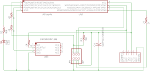
For this project I constructed a vacuum sensor circuit based on an ATMel ATtiny 45 micro-controller.Design:
The vacuum sensor board was design using Eagle CAD. In order to mount the vacuum sensor I first needed to create a new part footprint and add it to Eagle part library. Remaining footprints for components such as the ATtiny 45 were defined within the fab.lbr Eagle library.I used an existing 8 pin component as the basis of a new pressure sensor package and symbol and modified it.
Pressure sensor pads were resized and spaced according to its datasheet within the properties menu. Pin 1 was further distinguished with round solder pad corners to aid alignment on the board. Pins were also uniquely labeled and connected.
 |
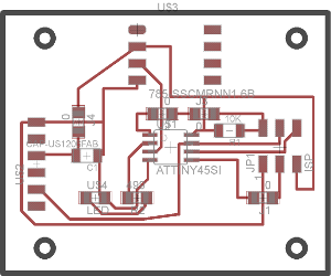 |
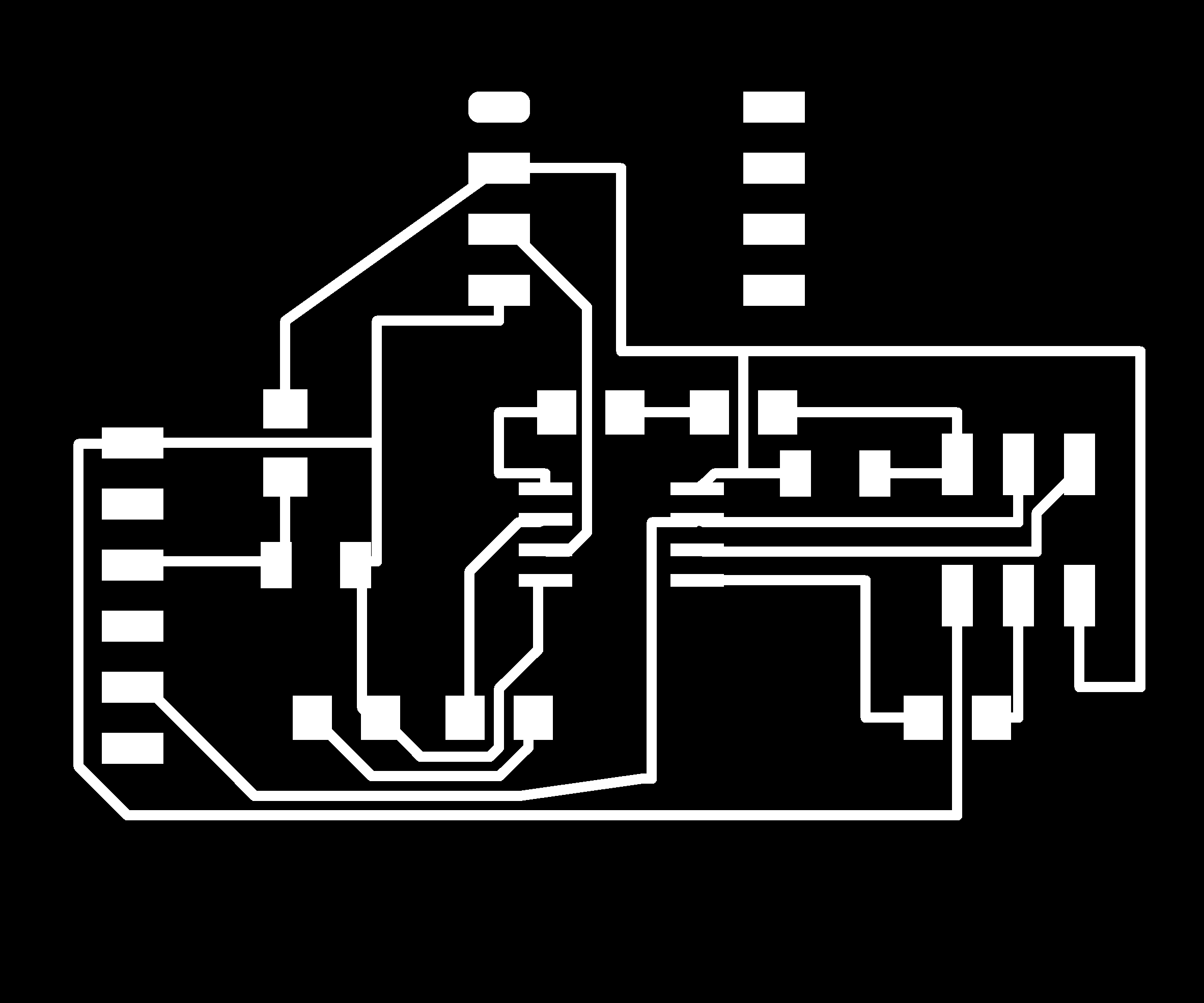
I used the Autorouting tool within Eagle to initially populate
most of the traces on the board after restricting the tool to
the top surface of the board for single-sided milling. I
refined the positions of some traces by hand and manually routed
traces the Autorouter was unable to place. To manually
route the missing traces four new 0 Ohm jumpers had to be
included into the Eagle schematic and positioned in the board
view.
As part of Autorouting the traces, I modified the Design Rule
Check (DRC) fields under the Tools tab to increase the
spacing between neighboring traces and pads to 0.016 in
(0.4mm). Despite this adjustment, four solder pads were
left fused together on the milled board when the end mill could
not travel between certain gaps.
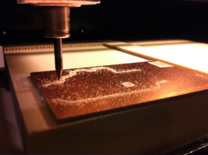
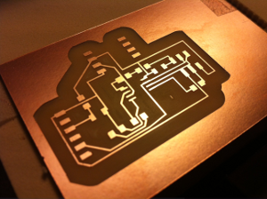
Fabrication:
The sensor board was fabricated from high resolution (1200 dpi)
black and white silhouette, PNG formatted images exported from
Eagle using the Roland Modela MDX-20 and Fab Modules. The
separate trace and perimeter files were cut with 1/64 inch
(0.40mm) and 1/32 inch (0.79mm) diameter end mills
respectively.
 |
 |
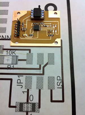
Areas not milled included the traces and neighboring pads of
the ISP 6 pin header. These features were manually
separated by cutting through the copper foil with a utility
knife and checking discontinuity with a multimeter.
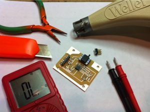
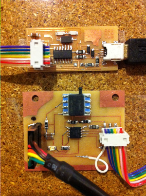
Programming:
While I identified and separated two of the fused pads prior to
stuffing the board, it was not until I attempted to program it
with the Fab ISP and experienced several initialization
failed errors when attempting to compile the sketch that I
reexamined the board again visually and with a multimeter and
discovered two more fused pads. The ISP header was heated
with a hot air gun and removed to separate the traces beneath
it. A wire jumper was used to bypass the trace torn from
the board while removing the ISP header. Repairs were
checked with a multimeter prior to reprogramming the
board.
 |
 |
 |
 |
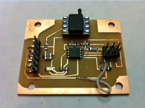
Separating the pads and traces resolved the error issue I
experienced when first attempting to communicate with the sensor
board over the Fab ISP. I used a simple Arduino sketch to
control the ATtiny45 to compare the measured sensor output
against a threshold integer and light a LED depending on the
relationship between the two.
Rather than a steady light from the LED set to HIGH I observed
a irregular flickering which I am troubleshooting.