MECHANICAL AND MACHINE DESIGN
AS220 FAB LAB, PROVIDENCE, RI
ASSIGNMENT: Propose a machine design with at least one axis, define and divide tasks among members of your group, automate your machine. Document your individual contribution and also as a group on your lab page.

The Egyptian Shaduf first appeared on an Assyrian king's seal in c.2000BC and is thought to be the first machine. It was used to draw water and is also known as a well pole. This ancient machine is still in use in many areas of Africa an Asia.
MACHINE PROPOSAL: PHOTO PRINTER
Build a photo printer that uses an LED light source "nozzle" that operates along two axis (x,y) system and renders a bitmapped image by exposing photographic paper.
INVENTORY OF PARTS
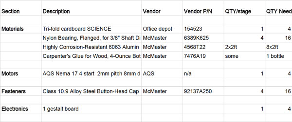
The BOM file is here and includes the following:
TASKS AND TEAMS
STAGE DESIGN & ASSEMBLY: Kenzo, Jessica & Jazz
DARK ROOM TESTING & LED NOZZLE FABRICATION: Simon & Lara
PROGRAMMING, UI, DOCUMENTATION: Jenny, Jill, Melitta & Matt
STAGE DESIGN & ASSEMBLY
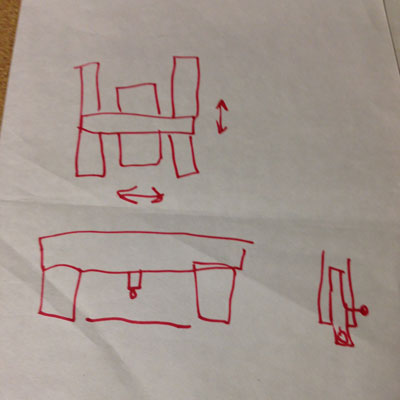
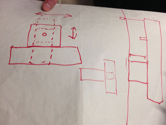
Initially, the design was going to use a 3 stage system in an "H" configuration, but then we realized we could accomplish our goals using a 2 stage system laid out in a "T" configuration. Here are some early drawings of the systems proposed:
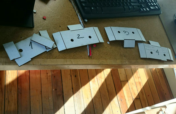
Fabricating the stages:
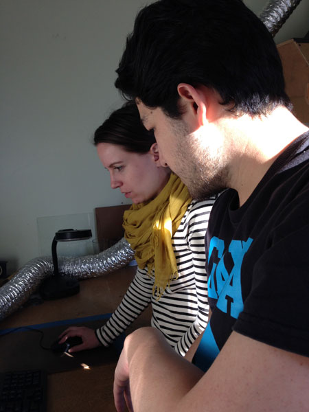
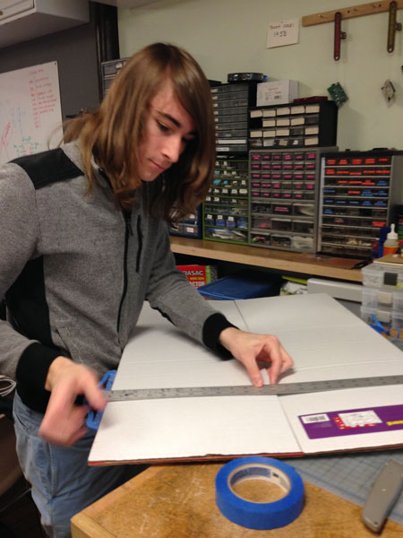
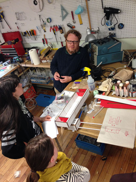
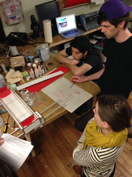
Brainstorming the possibilities for the stage design with Shawn:
DARK ROOM TESTING AND LED NOZZLE FABRICATION
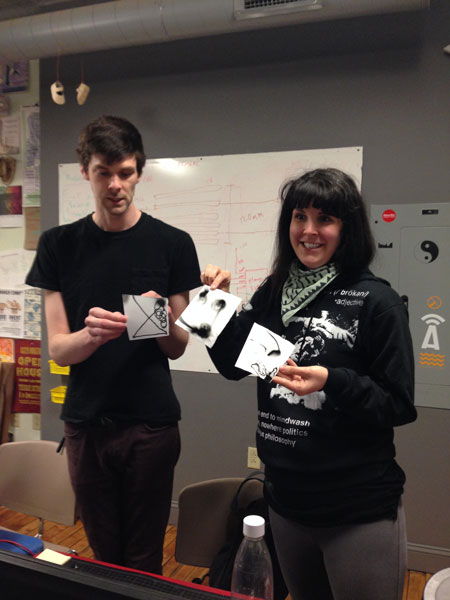
These are some of the cool results Simon and Lara had when exposing photographic paper to LED light:
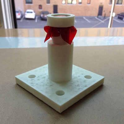
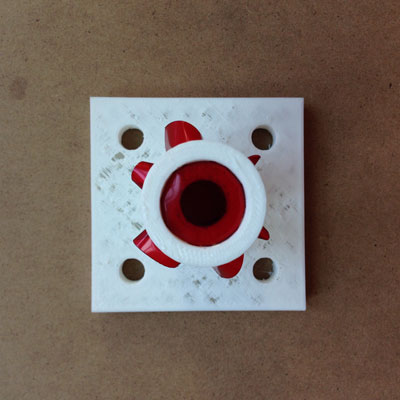
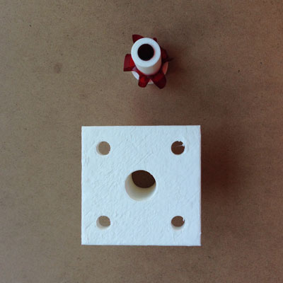
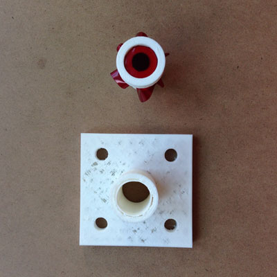
This is the elegant nozzle design that Simon modelled in OpenSCAD:
BOARD AND CABLE FABRICATION
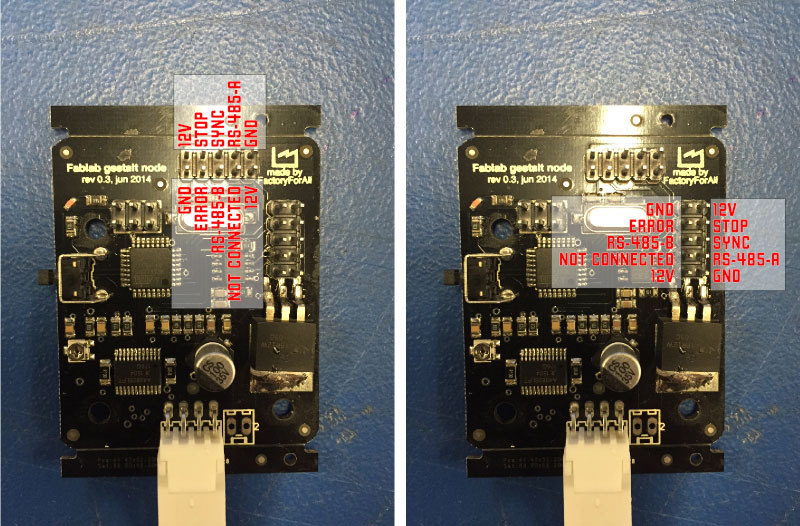
Fabnet uses an RS-485 bus with a few extra signals. From Shawn's tutorial, this is the pinout for a Fabnet header:
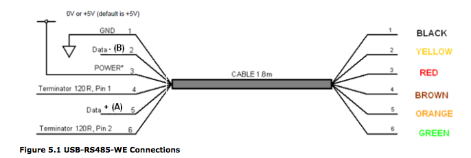
This is the pinout for the FTDI cable with the RS-485 bus:
In creating the tutorial, Shawn made a Bridge Board to adapt the (included) FTDI-RS485 cable to Fabnet and to provide power using these board files. He also added two 600 ohm pull up/pull down resistors.
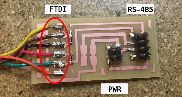
Node boards all have voltage regulators and get power (up to 12V for stepper motors) from the signal marked "HIGH." The RS-485 header on the right provides power, ground, and the A and B RS-485 signals (or plus and minus). Shawn notes that RS-485 uses differential voltage to help reduce noise.
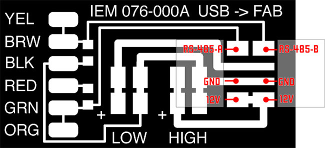
In addition to Bridge Board, Shawn also made the first cable, which connects the Bridge Board's RS-485 2x4 header to the Fabnet 2x5 header on the first Gestalt node:
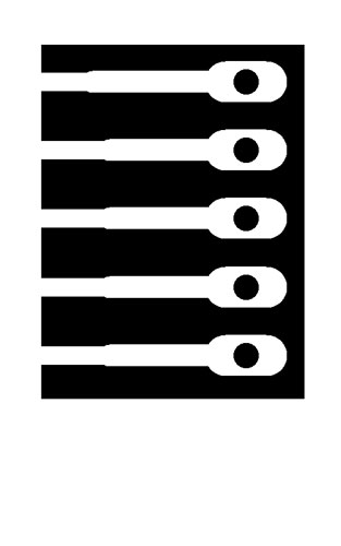
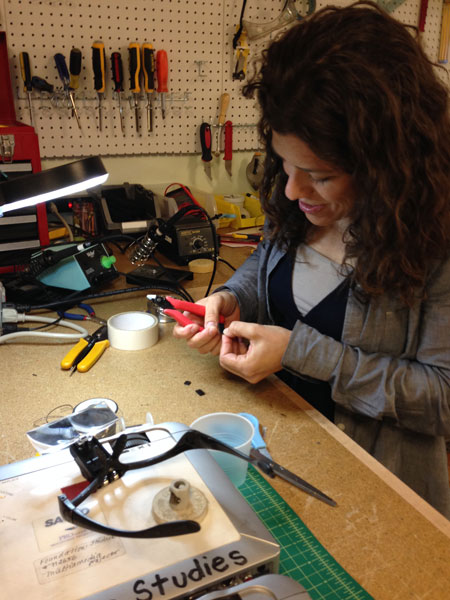
This first cable is not the same on either end, as noted in the pin-outs. The other node connecting cables are straight through, with pin-outs identical on either side of the cable. Melitta made these straight through serial cables with two 5 wire pcbs that were sandwiched together to create a 2x5 connector:

PROGRAMMING, UI, DOCUMENTATION
In addition to documentation of our group project, I helped with the set-up, testing and programming of the Fabnet and Gestalt nodes. I followed Shawn's tutorial and did the following:
Downloaded pygestalt code from: http://github.com/nadya/pygestalt.
Ran setup.py from the installation directory:
sudo python ./setup.py install
Next, I made the following hardware connections:
- Computer's USB port > USB side of FTDI cable
- Bridge Board side of FTDI cable > modified serial cable 2x4 connector side that Shawn made
- Modified serial cable hacked 2x5 side > Fabnet header on Gestalt node #1
- Stepper motor cable port on Gestalt node #1 > Stepper motor #1
Then, we attached power:
- Bridge Board power header > simple two wire power and ground connector
- Two wire power and ground wires > corresponding power and ground alligator clips
- Power and ground alligator clips > power and ground bendch supply.
Last, we turned on the bench power supply and adjusted it to approximately 12 volts.
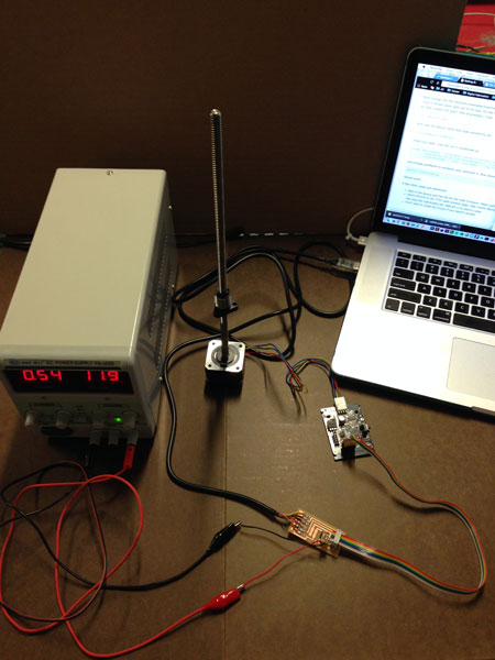
Then, I found device ID of FTDI cable assigned by my computer:
ls /dev/tty.usb*
Edited singlenode.py portname to reflect device ID of FTDI cable:
  else: self.fabnet = interfaces.gestaltInterface('FABNET',
	  interfaces.serialInterface(baudRate = 115200,
	  interfaceType = 'ftdi', portName = 'dev/tty.usbserial-FTXW7FE2'))
Downloaded and installed Pyserial using these instructions from Adafruit for MacOS: https://learn.adafruit.com/arduino-lesson-17-email-sending-movement-detector/installing-python-and-pyserial
Finally, I ran gave the command:
python singlenode.py
I was prompted to press the button of the Gestalt node to identify it and initially had an error, but forgot to document it. I removed the persistence temp file and tried again. This time the motor started spinning!
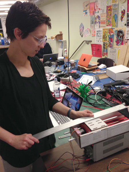
Kenzo and Jessica gave us a working stage with a motor and Jenny and I played with the single_node.py code to find a stop point. We determined that the maximum distance for the motor to move along the x axis was approximately 10 inches.
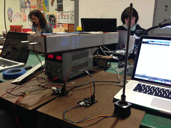
We found that if we adjusted the second coordinate specified in the supercoords array (???) that we got about one inch of movement for every 20 units.
if __name__ == '__main__':
        stage = virtualMachine(persistenceFile = "test.vmp")
        #stage.xNode.loadProgram('../../../086-005/086-005a.hex')
        #stage.xNode.setMotorCurrent(1)

        stage.xNode.setVelocityRequest(8)

        #f = open('path.csv','r')
        #supercoords = []
        #for line in f.readlines():
        #       supernum = float(line)
        #       supercoords.append([supernum])

        #20 = 1 inch
        #supercoords = [[10],[20],[10],[0]]

        #40 = 2 inches
        #supercoords = [[10],[40],[10],[0]]

        #60 = 3 inches
        #supercoords = [[10],[60],[10],[0]]

        #100 = 5 inches
        #supercoords = [[10],[100],[10],[0]]

        #190 = 9.5 inches
        supercoords = [[10],[190],[10],[0]]

        #200 = 10 inches
        #supercoords = [[10],[200],[10],[0]]

        for coords in supercoords:
                stage.move(coords, 0)
                status = stage.xAxisNode.spinStatusRequest()
                while status['stepsRemaining'] > 0:
                        time.sleep(0.001)
                        status = stage.xAxisNode.spinStatusRequest()
Our next task was to get the second Gestalt node working, which will control the y axis of our photo printer. We turned off the bench power supply and made the following connections:
- Fabnet 2x5 header on Gestalt node #1 > 2x5 connector of hacked pass-through serial cable that Melitta made
- Other end of 2x5 connector of hacked pass-through serial cable > Fabnet 2x5 header on Gestalt node #2
- Stepper motor cable port on Gestalt node #2 > Stepper motor #2
Then, we turned on the bench power supply. We navigated to pygestalt-master/examples/machines/htmaa and ran the test code xy_plotter.py:
python xy_plotter.py
Both motors ran successfully!
IT'S A MACHINE!
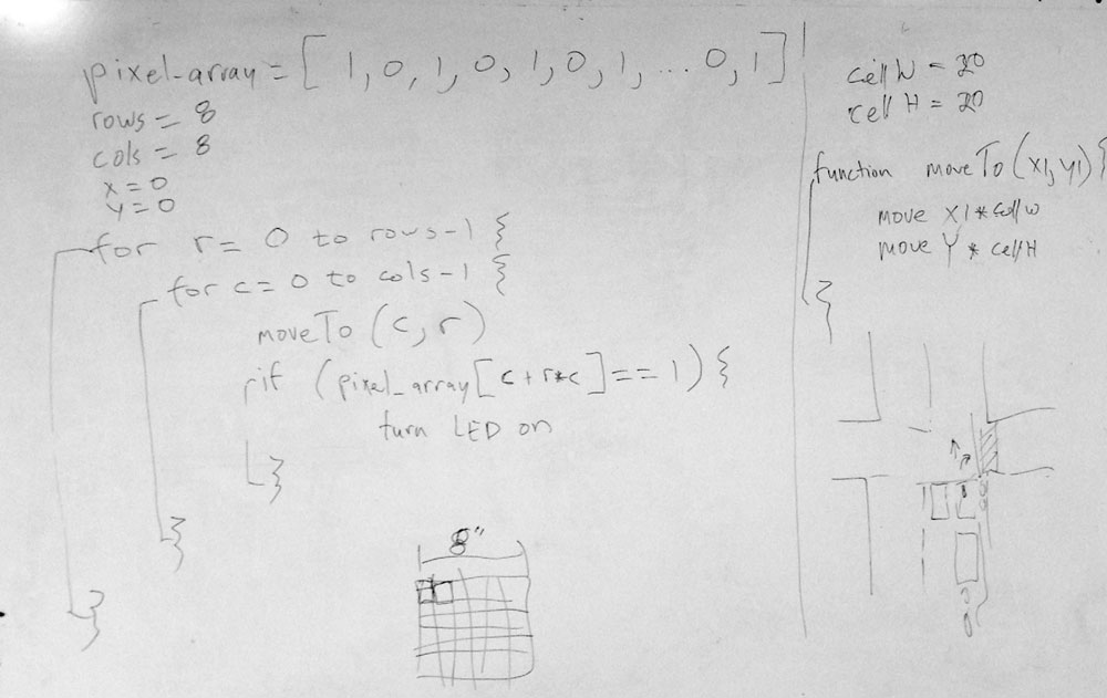
Shawn provided the following psuedo-code to get us started on thinking about how our machine could become an LED light printer:
He also found this Processing example as a starting point for our photo printer code.
We decided to use an Arduino to control the blinking of the LED, but in order for the Arduino IDE to work with Python, we had to download and install Pyfirmata and install the Pyfirmata Arduino library. We also attached a felt tip marker to the underside of our moving stage to simulated the motion of the LED.
The xy_plotter.py script was modified to import the pyfirmata library:
#------IMPORTS-------
from pyfirmata import Arduino
We also tested the range of movement:
	# Some random moves to test with
        # moves = [[10,10],[20,20],[10,10],[0,0]]
        moves = [[100,100],[20,20],[150,150],[0,0]]
We told the script the device name of the Arduino:
	# Connect to the Arduino.  Find out port, new arduinos are dynamic tty assignment
	LEDboard=Arduino("/dev/cu.usbmodem1451")
In this part of the script, we told the machine to move the pen incrementally along an 8x8 grid. Once we got it working, we substituted the LED for the felt tip marker and told the script to flash the LED at every coordinate point, but to turn it off during the travel period. Once the coordinates had been cycled through, we told the machine to move the LED back to the origin:
        # Move!
        for row in range(0,7):
                for col in range(0,7):
                        #specifies cell width
                        stages.move([col*-20,row*20], 0)
                        status = stages.xAxisNode.spinStatusRequest()
                        #checks to see if the move is done


                        while status['stepsRemaining'] > 0:
                                time.sleep(0.001)
                                status = stages.xAxisNode.spinStatusRequest()
                        LEDboard.digital[11].write(1)
                        #where we change time LED is on
                        time.sleep(.01)
                        LEDboard.digital[11].write(0)

        # Travel home, go to 0,0 and waiting for node to say i'm at 0,0
        stages.move([0,0], 0)
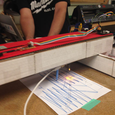
We were reminded that python cares about indents and experimented with syntax! Here is a picture of our light printer working with an orange LED:
TAKING IT TO THE NEXT LEVEL... PHOTOGRAPHIC PAPER & PROGRAMMING EXPERIMENTS
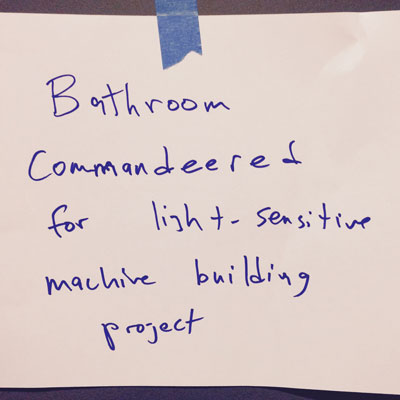
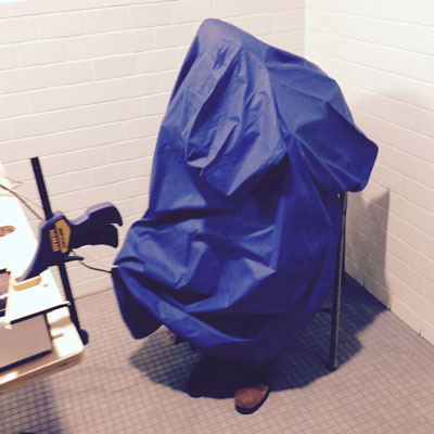
Our goal was ultimately to make an LED light printer that could process a bitmapped image and expose photographic paper in on/off bits. We found a nice dark space in the bathroom and set up shop. The laptop and I got "tented" with a rain poncho to minimize light from my laptop when lights were off.
Kenzo, Jessica and Melitta setting up and testing our machine:
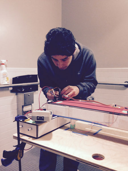
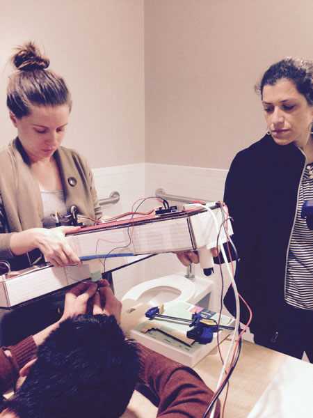
It wasn't possible to photograph our printer working in the dark, for obvious reasons, but we found that the 1 second exposure time worked the best with our coarse grid:
Here is the python script we used and we also made a video showing our machine working. We experimented with using a finer resolution, but had several errors that we haven't yet been able to debug.
IMG 7006 from jill hartley on Vimeo.
PRINTING A BITMAP WITH LIGHT: MAN RAY MACHINE
The code was updated so that it reads an image and plots it using the LED print nozzle. It can be downloaded here. Also, some code to move axes with keys on the keyboard was written (but not tested):
from msvcrt import getch

# loop to allow for control of the machine using the keyboard (arrow keys and escape key)
# adapted from http://stackoverflow.com/questions/12175964/python-method-for-reading-keypress
# key codes from http://infohost.nmt.edu/tcc/help/pubs/tkinter/web/key-names.html
while True:
    key = ord(getch())
    if key == 9: #ESC
        break
    elif key == 98: #up arrow
        stages.move([xPos, yPos + 1], 0)
        status = stages.xAxisNode.spinStatusRequest()
                # This checks to see if the move is done.
                while status['stepsRemaining'] > 0:
                    time.sleep(0.001)
                    status = stages.xAxisNode.spinStatusRequest()
    elif key == 100: #left arrow
        stages.move([xPos - 1, yPos], 0)
        status = stages.xAxisNode.spinStatusRequest()
                # This checks to see if the move is done.
                while status['stepsRemaining'] > 0:
                    time.sleep(0.001)
                    status = stages.xAxisNode.spinStatusRequest()
    elif key == 102: #right arrow
        stages.move([xPos + 1, yPos], 0)
        status = stages.xAxisNode.spinStatusRequest()
                # This checks to see if the move is done.
                while status['stepsRemaining'] > 0:
                    time.sleep(0.001)
                    status = stages.xAxisNode.spinStatusRequest()
    elif key == 104: #down arrow
        stages.move([xPos, yPos - 1], 0)
        status = stages.xAxisNode.spinStatusRequest()
                # This checks to see if the move is done.
                while status['stepsRemaining'] > 0:
                    time.sleep(0.001)
                    status = stages.xAxisNode.spinStatusRequest()
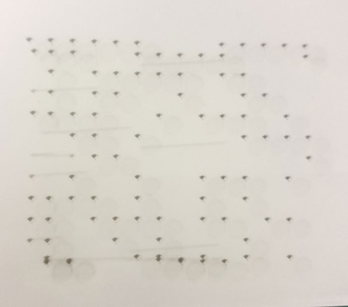
Here is the bitmapped file used, which is only 15x15 pixels.
This is the result of our LED light plotter!
RELEVANT LINKS: