NETWORKING AND COMMUNICATIONS
JILL HARTLEY YOKOTA, AS220 FAB LAB, PROVIDENCE, RI
ASSIGNMENT: Build a wired or wireless network connecting at least two microcontrollers.
CLASS PROJECT
Shawn suggested we do a class project combining this assignment and next week's Applications and Interfaces assignment. He proposed building a WiFi network with each of us creating a board integrating the ESP8266 shield for this week's work. Next week, we will output the communication of these boards to a web page.
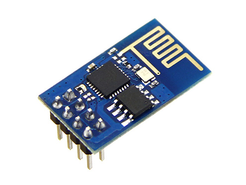
ESP8266 NOTES
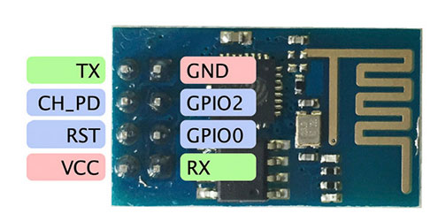
The ESP8266 is an 802.11b/g/n WiFi "system on chip" (SOC) and can provide internet-enabled services to a microcontroller by programming the firmware with the AT command set and using serial UART, or as a standalone WiFi-enabled microcontroller by programming the firmware with the software development kit (SDK). It also includes a built-in temperature sensor.
GPIO pins include analog and digital IO, PWM, SPI, UART, I2C.
The ESP-01 (shown below) is the simplest and least expensive ESP8266 board (~$2.50 each):
BUILDING THE MICROCONTROLLER BOARD
Shawn created an initial design on the board for us to follow in creating our Eagle schematic:
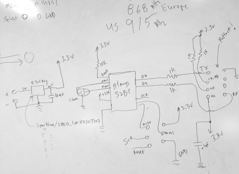
We had lots of challenges with this design and it was amended and hacked several times throughout the week.
The issues we had included:
Voltage regulator switcheroo. The 3.3v regulator specified in the Fab inventory changed footprint and did not align with the milled board traces of the original package. Shawn sent a recommended 1A substitute from the Modern Device lib named V_REG_LDOSMD (V_REG_LDO) in the SOT23-5 package.
Microcontroller confusion. The Eagle part specified for the microcontroller initially was the ATMEGA48/88/168-AU (ATMEGA48/88/168) in the TQFP32-08 package from the 01_atmega8 library. This part created pads that were too thick and so the ATMEGA88-THIN microcontroller in the TQFP32-08THIN package from the fab2 library was substituted. The actual microcontroller component used on the board was the ATMEGA328p.
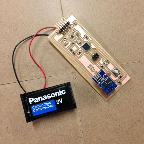
ESP8266 mirroring. Our plan was to solder the ESP8266 to the underside of our microcontroller board. We mirrored the part in the schematic, but found that Eagle does not mirror the part in the board view. We used a socketed header and mounted it on the top of the microcontroller board and got the orientation figured out after our boards were milled. It turned out to be a "happy accident" because now the ESP8266 can be used with other boards.
FTDI header. Somehow we missed including an FTDI header in the board design, which provides a serial connection and is necessary in order to power and debug the WiFi connection.
EAGLE FILES
With all the changes incorporated, this is the Eagle schematic I came up with:
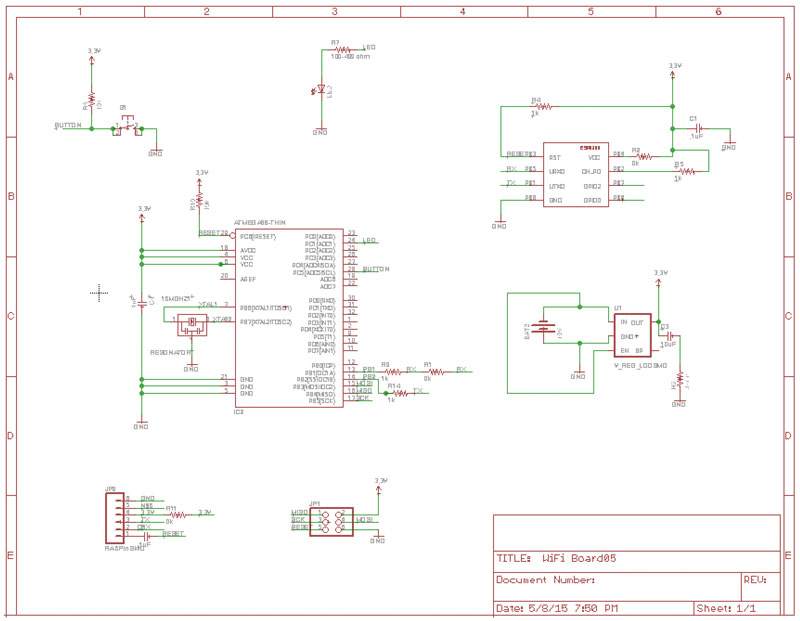
...and here is the board design.
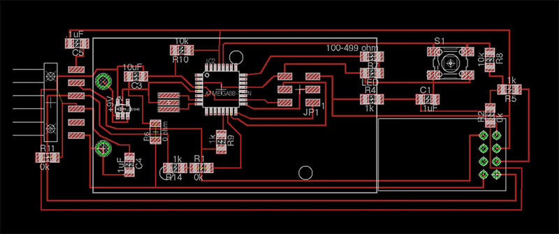
The Eagle files can be downloaded here.
ASSEMBLING THE PARTS
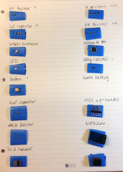
MILLING THE BOARD
We all had problems milling these boards. The traces had to be very tiny around the microcontroller (0.01mm) which is tricky for a 1/64th endmill to create in some of these very tight spaces. We do not have the smaller endmills in our lab because Shawn said that they break too easily. He suggested trying the default toolpath diameter of .25mm in the Fab module for 1/64th endmill.
Unfortunately, the traces got ripped up under these settings:
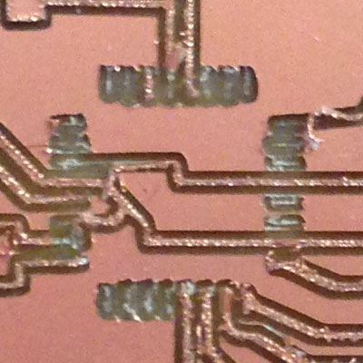
I had the same issues on my button board, although only the traces not going anywhere fell off and I was able to salvage the ones still connected. On this board, traces that were "in use" in the schematic design and attached to components also fell off. This was very frustrating. Kenzo did an experiment creating longer pads for the microcontroller pins, which seemed to preserve them better under these circumstances. I will try his trick the next time.
Next, I tried milling the board using the .4 mm toolpath diameter and the 1/64" endmill, which was another Kenzo suggestion. This tricks the mill into thinking it has a larger endmill and creates slightly wider traces. This worked better and all of the traces around the microcontroller that were a part of the circuit design were preserved. There was one floating trace that I attempted to repair with solder and Guerilla Glue (we had no Super Glue in the lab). The glue didn't hold, but the fixtured microcontroller seems to have stabilized the trace.
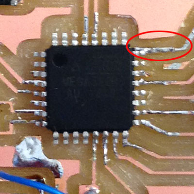
Here is the finished microcontroller board with the ESP8266 acting as shield:
TESTING THE BOARD
Another challenge we've had has been with the reliability of both our FabISP and the two class "store bought" programmers.
Here are the steps I followed to test the board:
- attach the 2x3 serial pin cable of the programmer to the programming header, aligning the red stripe with pin 1.
- provide power by attaching the 9 volt battery
- open Arduino IDE 1.6.3, go to the Tools menu:
- microcontroller > Arduino Uno
- port > USBserial
- programmer > USBtinyISP
- then choose "Burn Bootloader" from the Tools menu.
Here are the types of errors I got with the various programmers using the settings above:
My Programmer:
avrdude: stk500_recv(): programmer is not responding
avrdude: stk500_getsync() attempt 1 of 10: not in sync: resp=0x00
Black Programmer:
avrdude: initialization failed, rc=-1
Double check connections and try again, or use -F to override this check.
Error while burning bootloader.
Blue (AVR) Programmer:
(Used AVR ISP from Programmer menu)
avrdude: stk500_recv(): programmer is not responding
avrdude: stk500_getsync() attempt 1 of 10: not in sync: resp=0x00
Problem uploading to board. See http://www.arduino.cc/en/Guide/Troubleshooting#upload for suggestions.
This report would have more information with "Show verbose output during compilation" enabled in File > Preferences.
I used the multimeter to test all of the components and circuits and found one broken and loose trace. I tried to fix it with solder, but to no avail, so I created a little jumper wire to complete the circuit.
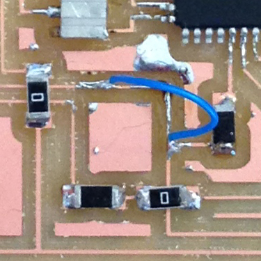
Unfortunately even after I fixed this circuit, I still couldn't download the bootloader and had the same errors. I ran out of time to debug further and had to move onto next week's assignment.
RESOURCES
Getting Started with ESP8266 by Seedstudio