EMBEDDED PROGRAMMING
JILL HARTLEY YOKOTA, AS220 FAB LAB, PROVIDENCE, RI
ASSIGNMENT: Read a microcontroller data sheet and document what was learned. Program ATtiny board to do something using at least one programming language. Describe programming process and link executable code.
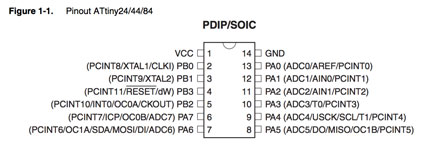
WHAT WAS LEARNED READING MICROCONTROLLER DATA SHEET?
I did not understand much when reading the data sheet for the Atmel ATTiny22/44/88 microcontroller initially. I am reviewing it again on the eve before final presentations and understand a bit more, but still there is much to learn about microcontrollers. A suggestion for future classes would be for FabAcademy to host voluntary review session(s) to go through this data sheet more thoroughly and to facilitate understanding of the most relevant microcontroller information, especially how it relates to selecting a microcontroller(s) for final project purposes. The most relevant information seems to be:
8-bit microcontroller
RISC architecture
2/4/8kb of flash, so pay attention to how much memory your Arduino sketch requires
in system programmable via SPI port
12 programmable I/O lines
operating voltage 2.7 - 5.5V for Attiny 25/45/85
pull-up resistors are internally supported on the port b lines
PROGRAM THE BOARD
Arduino IDE was configured to use the ATtiny84, 20MHz resonator with the TinyISP. I tested with Shawn on his laptop. When the LED+SWITCH board was plugged into the computer's USB port with FTDI cable, the microcontroller did not get hot.
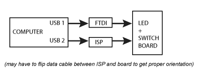
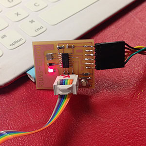
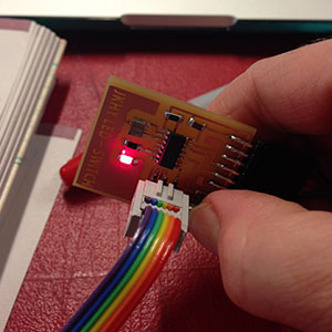
Next, the USB extender was plugged into the FabISP and the other USB port on the computer. The ribbon cable was connected to the programming headers on both the FabISP and LED+SWITCH board. The connectivity looked like this:
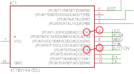
The "Blink" sketch was modified to use pin 7, which was the corresponding LED location on the ATTiny44 schematic:
The program was compiled and we got an error that the "FabISP Tiny could not be found." We tried rotating the programming header, various cables and ISPs, performed another visual inspection and Shawn found that one of the traces on the microcontroller was connected to a neighboring trace erroneously. I removed the microcontroller and used an exacto knife to cut out the small trace protrusion. I soldered the microcontroller back on to the board and we tested again. We had the same result.
Nadya showed me how to use a multimeter to check connections:
Set to "diode" and power on
Put one probe on ground and other probe on each pin
If it beeps, it means that pin is connected to ground. Is it supposed to be? Check schematic. If pin is not supposed to be connected to ground, check the solder joint and correct.
Kenzo helped me to further debug the board. Eventually we found the problem to be with the resonator, which was erroneously soldered to ground on the first and third pins. The resonator was removed and the Arduino IDE changed to use the 8MHz internal resonator instead. The problem loading the compiled "Blink" sketch persisted, although it did run once. We found the program was still looking for a 20MHz external resonator, even though we had specified an 8 MHz internal.
I soldered a new resonator on the board and tested with the multimeter. We then had success downloading the "Blink" sketch! I also played with the "Switch" sketch and was able to use the button to turn the LED on/off. The button was assigned to pin 3, according to the pin translation schematic (above). I also got the "Fade" sketch to work without any troubles.
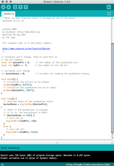
ARDUINO IDE CODE: