ELECTRONICS DESIGN
JILL HARTLEY YOKOTA, AS220 FAB LAB, PROVIDENCE, RI
ASSIGNMENT: Redraw the "echo hello world" board. Add a button and LED with current-limiting resistor. Describe and take pictures of the process.
USING EAGLE TO LAYOUT THE BOARD
I downloaded and installed Eagle and the fab libraries. Using Eagle was difficult, but manageable once it's nuances were pointed out. I followed Anna's tutorial to complete the assignment. It was well documented and helped to point out many of the Eagle usability issues.
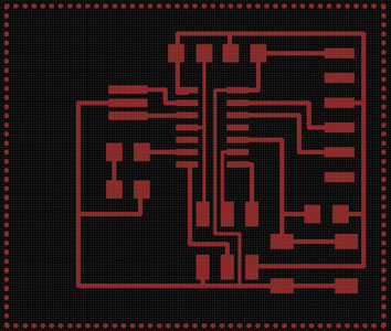
First, I imported the components necessary from the library, then laid them out according to Anna's example. Next, I labeled each component and the pins, which built the trace references in the file. This is what it looked like in Schematic view:

The next step was to view the file in Board view and to route the traces. I did this manually and followed Anna's suggested layout closely. I had some remaining yellow air wires once completed and consulted with Kenzo about why that might be. He showed me that the program cares about the orientation of all components, whether it matters or not. We flipped the orientation of a capacitor and resister, recreated some of the traces and solved some of the routing issues. The others were addressed by recreating some of the traces that consisted of multiple segments.
Shawn also taught us a trick to create more ground surface area on the board. One uses the polygon tool to trace the outer edge of the board design and then applies the rat's nest tool to the polygon. This fills in most of the empty space on the board with copper and also allows one to easily label the board next in Photoshop.
CREATING BITMAPS IN PHOTOSHOP
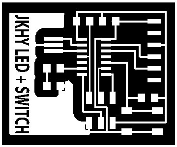
The board was exported as a .png file and opened in Photoshop. A 20 px white border was created and a label with my name on it was applied to the empty copper space. Also, a second file was created just containing the cut path of the board.
MILLING THE BOARD ON THE MODELLA
We had to create a new sacrificial masonite board for the Modella, since the last one was pretty destroyed. We measured the board and cut two of them on the laser cutter. They were attached to the Modella's bed with double stick heavy duty tape. The sheet of PCB board was attached to the masonite using double stick tape, as well.
The fab module was loaded and the file for the board prepared. The milling bit was changed to 1/64 and the instrument positioned to the surface of the material. The board was printed without any issues and the milling bit changed to the 1/32 version and the file with the border loaded into the fab module.
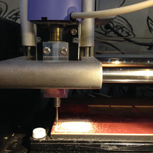
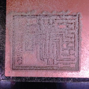
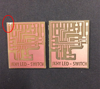
All went well until the very last border corner when the PCB board lifted and the milling bit damaged the corner of the PCB. We think the problem was that the PCB board was lifted once after attached to the sacrificial board and that it may have weakened the strength of the double stick tape. We went through the process again and this time the PCB and it's border were milled successfully.
STUFFING THE BOARD
The components necessary to stuff the board were identified, labeled and taped down to a sheet of paper, including:
2x3 programming header
ATtiny84 microcontroller
1x6 FTDI header
20 MHz resonator
2x10k resistors
Omeron switch/button
red LED
1k resistor
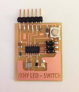
The soldering was slow going and tricky due to the small trace sizes especially around and under the microcontroller. After the components were attached, I visually checked the connections and compared once again to the board design. Next, it was time to test and run some programs, which I did as a part of the Embedded Programming assignment.
THE FINISHED BOARD
DESIGN FILES:
Here are the Eagle files, border file and png to make my board.