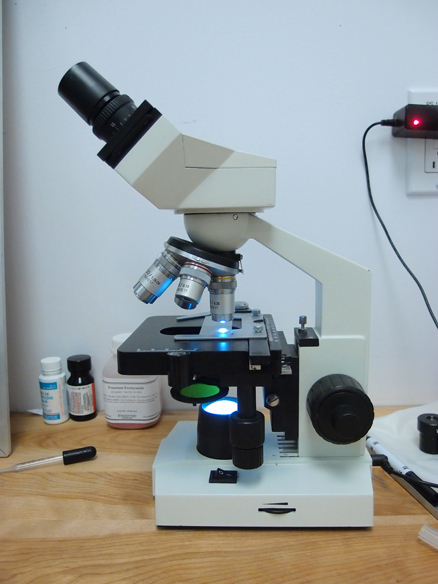
For my final project I decided to keep what I first proposed the first week of fab academy. Add numerical control to my microscope. But instead of connecting motors directly to the original XY knobs, I decided to simply build a stage that would sit on top of the original one and build a webam mount. So what will it do.. it would allow me to scan complete slides and merge them all to create a huge view of the slide.
It would also allow me to track moving things using blob detection, record movement and use it for wathever I can think of. If properly calibrated, I could also measure the speed of microorganism and detect patterns in movement maybe. But First of all, I should build the stage and see where this can go.
2. Who's done what beforehand?
Some companies have developped this kind of motorized stage, mostly quite expensive ones for high-speed, precise applications. That's not exactly what I'm looking for. Edmund optics sells one for 5,500$ minus the 995$ controller.. there is also an opensource design called OpenStage.. but not really what I need. But I see a flexible coupler attached to the motor, that's a confirmation it can be used.
3. What materials and components will be required?
For the initial design I was planning on using a pair of stepper motors connected straight to the original knobs using a wormdrive I would have designed but I decided to build something that could sit on the original stage so it can easily be adapted to any other microscope.
I'm still thinking about what type of actuators to use, standard DC motors with encoders or stepper motors. I will also need a webcam to mount on the microscope. Everything else will probably designed out of MDF, plywood or acrylic.
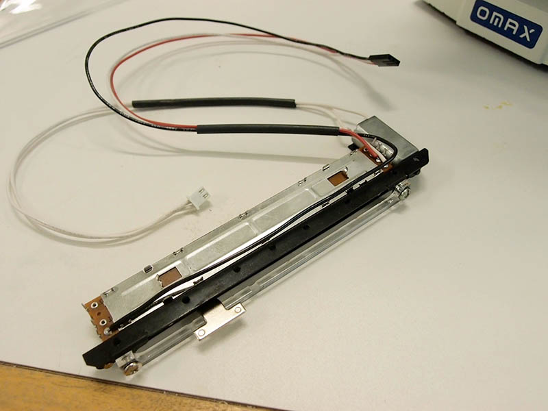
UPDATE: I decided to use motorized slide potentiometers. A motor is attached with a belt to the wiper of the potentiometerso when you turn the motor on, the potentiometer value changes, this could be used for precise control.
4. Where will they come from?
We have a couple of DC motors that could be used for this project laying in the lab and stepper motors are available in a local electronic shop. They sell 3D printer kits.
UPDATE:There's this place called RobotShop not too far from the Lab, they sell all sorts of robot parts and the have linear taper motorized slide potentiometer. They're 25$ each. Which brings the grand total of my expenses for this project to around 60$ including shipping.
Dual H-Bridge to drive the DC motor in the slide pots. Got a few L293D
12-24V power Supply to drive the motor. Got a couple
WebCam. Got One
Computer. Got One.
6-8. What parts and systems will be made?
I will design a PCB that will connect to the Sippino
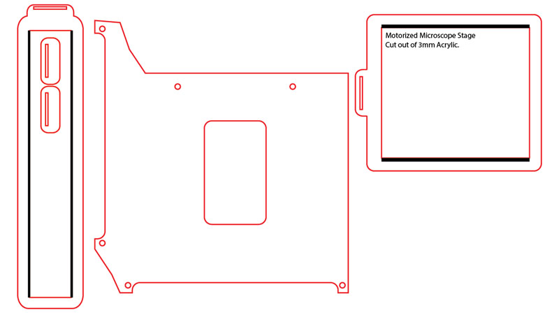
I will design the custom Stage that will attach to the existing microscope stage.
7. What processes will be used??
Laser Cutting
PCB design + Milling
Application Programing
3D printing for the WebCam Mount
8. What tasks need to be completed?
Design and mill the pcb that will control the axises
Design the XY motion structure (as tiny as possible...)
Program the setup so it can receive commands from the serial port
Program a Processing application that will send movement to the stage
Program a Processing application that will send movement to the stage using the input from a web cam as a motion detection and bring it into focus.
9. What questions need to be answered?
How precise will it be
How hard is it to move the slide around using my design
How fast can it go
10. What is the schedule?
The schedule is pretty much to finish everything before the end..
11. How will it be evaluated?
For the project to succeed I have to be able to take pictures of the whole surface of the slide. Automatically..
BUILDING PROCESS
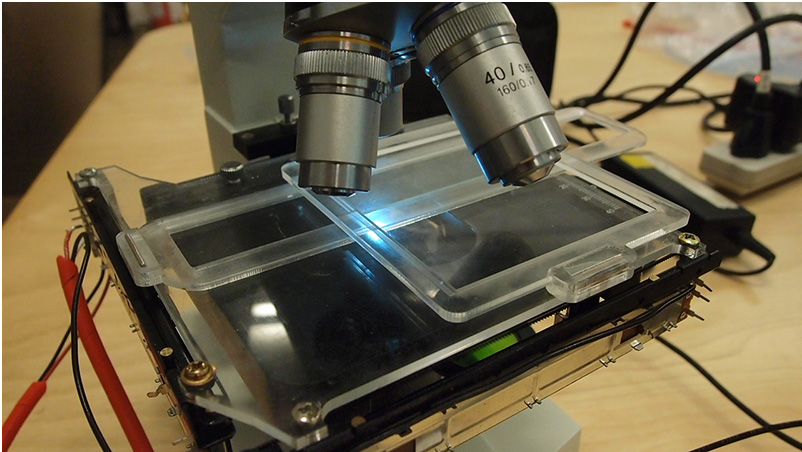
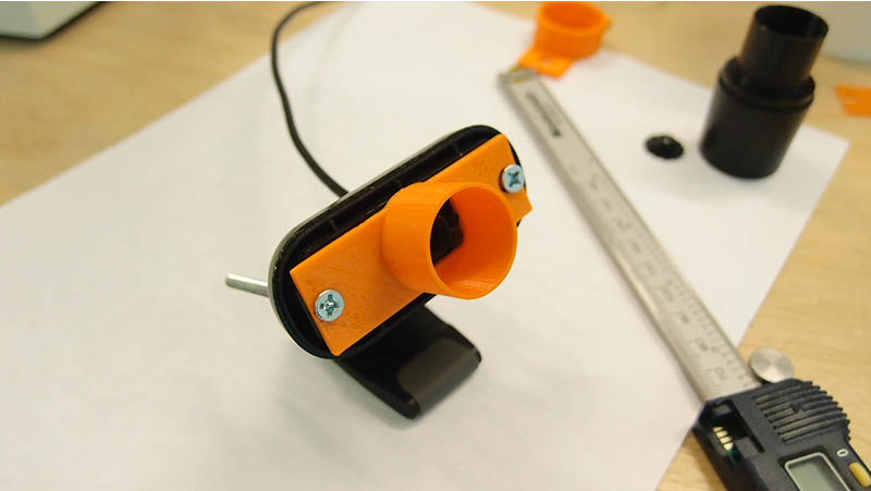
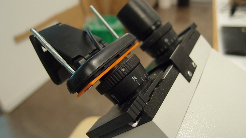
Here's what it looks like assembled.
For the design I decided to use motorized slide potentiometers like this one.
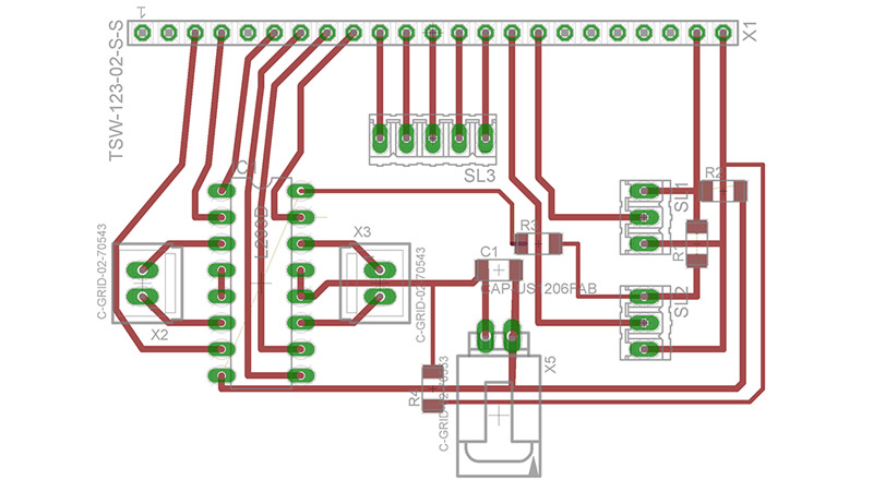
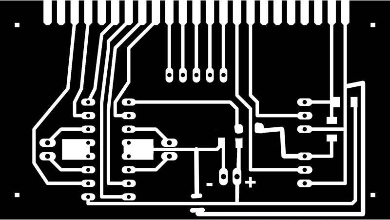
It's linear motion with constant feedback. It's perfect to precisely move small things around as it's outputing analog values according to it's position. I bought 2 of these, one for each axis. They're also pretty small which is perfect since my project has to be really thin if I still want to be able to focus everything. The space between the optics and the stage is one of the key factor that kept me from adding stepper motors and a full XY bed.. the thing shouldn't be more than 1cm or 2cm thick. To drive these, I use a dual H-Bridge chip, the L293D. It makes it really easy to drive and PWM motors to vary it's speed. I also need to connect both potentiometers to the analogPins of my Sippino so I designed a board that would act as an interface between my slide pots and my arduino leaving room for some eventual evolution. I also placed a row of holes that could be used to add buttons to manually jog the stage.
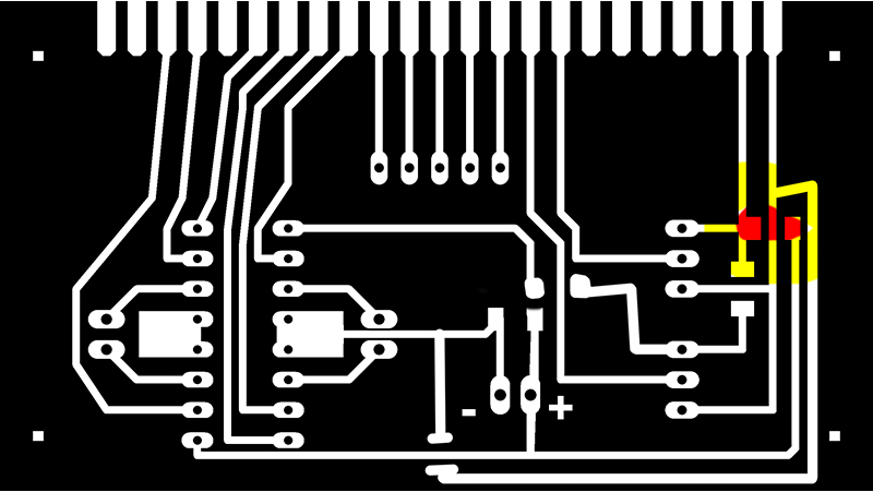
!!!!THIS JUMPER SHOULD ONLY BE SOLDERED IF THE MOTOR POWERSUPPLY IS 5V!!!!
It's a problem in the design I figured out later, at first when I was playing with the motors 5V seemed enough, but with the sliders attached I'm using an 18v power supply... which would fry the arduino and possibly the usb port in a flash..
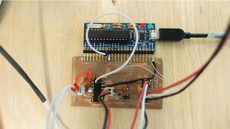
Here's the final product, a Sippimno soldered to my interface board. yes... I did some rework on the board when I realised some traces shouldn't be touching, or should touch. Actually 3 of the.. I had missed a ground connection on the L293D, I ripped the trace on one of the direction pin so I had to use a jumper cable to carry the signal and I finally since I moved to 18v instead I had to power bridge the 5V from the arduino to the chip as I was powering the chip from the external powersupply... after making sure traces were where they had to be, I plugged everything and started coding a really basic code to see if everything worked:
if(analogRead is smaller than 10)digitalWrite blablabla
Both slide pot worked fine
It was time to design the stage so I started by removing the slide holder which is held in place by 2 screw right on top of the original stage, which also happen to be a perfect spot to attach my own.
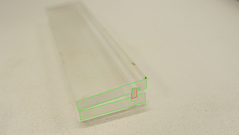
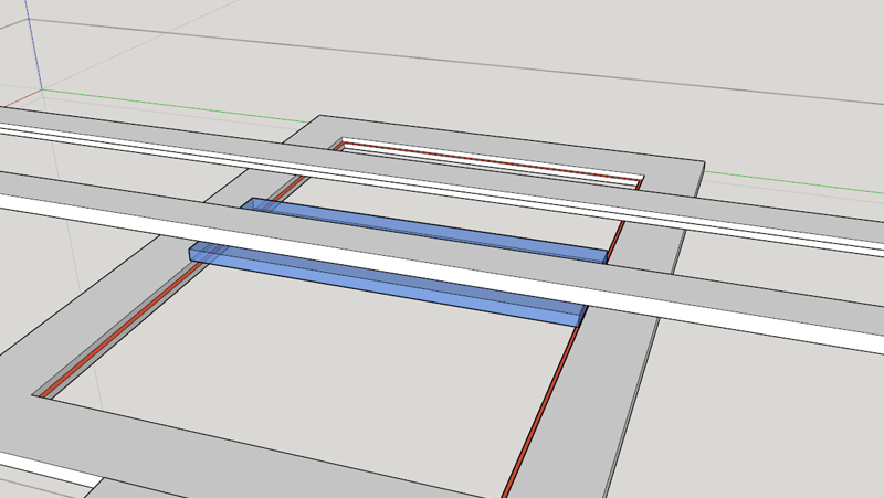
For the linear motion I tried to make some tracks out of acrylic that could ensure that everything is moving straight. With this design however, the second slider should be fixed on a moving part putting more load on the first motor. But I gave it a try just to see how much friction there is between two pieces of acrylic.
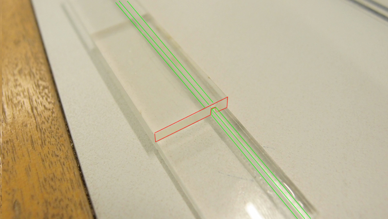
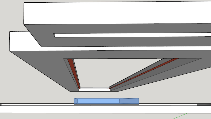
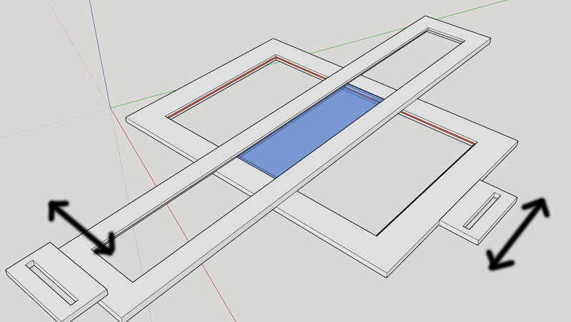
This last test worked pretty well, I slightly increased the size of the groove on the top one while gluing the rail to the bottom. But I had a better idea for the motion. Since microscope slides are so light and easy to move around, I tought I'd use 2 peices of acrylic on top of each other to guide the slide where I want it to be.
Stage Design
Not perfect but stable enough to move the slide and bring it back pretty much to the same place.
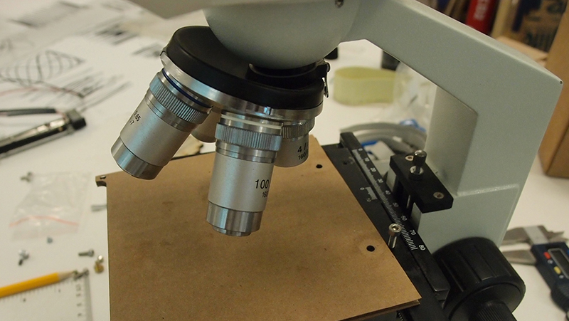
I used 3mm acrylic to build the stage, everything assembled is aproximately 9mm thick with the slide laying at aproximately 6mm above the original, stage so there's still plenty of room to experiment with thicker samples like microchips.
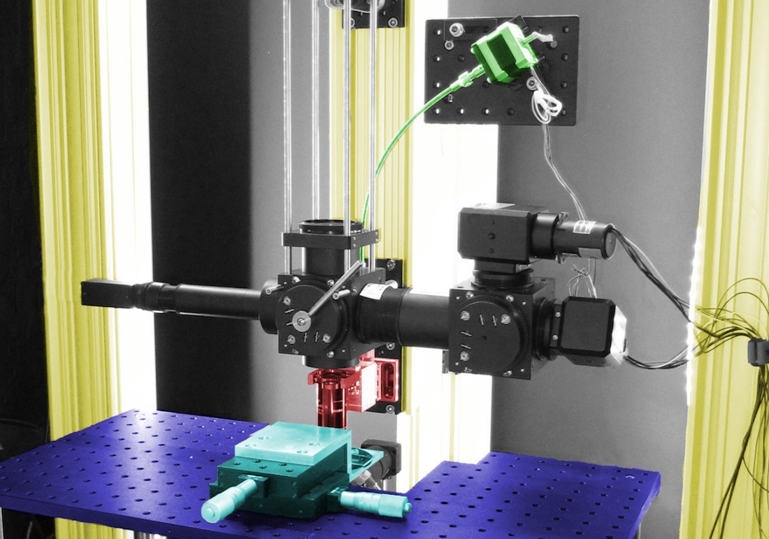
WebCam Mount
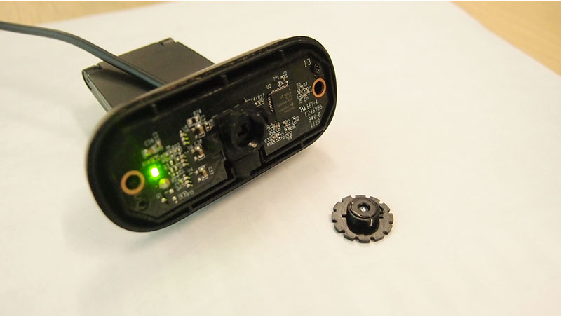
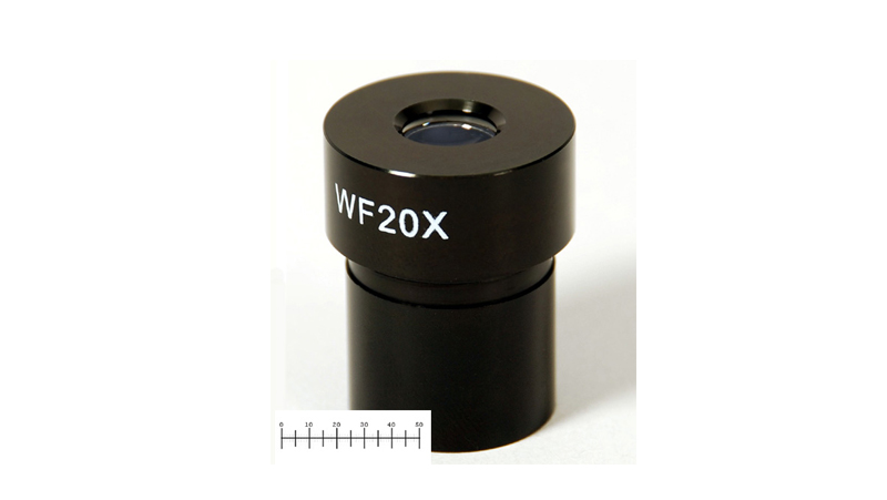
For the webcam I had an old Logitech C210 laying around. I opened it up, and removed the lens as without it I get much clearer pictures and the image is not constrained in a small circle in the middle of the picture. Took some measurement, 6cm wide, holes needed to be 5cm appart, with a 2x1.5cm rectangle in the center. I then added the miscoscope's eyepiece's cylinder to it, eyepeice's diameter was aproximately 23mm and 15mm long.
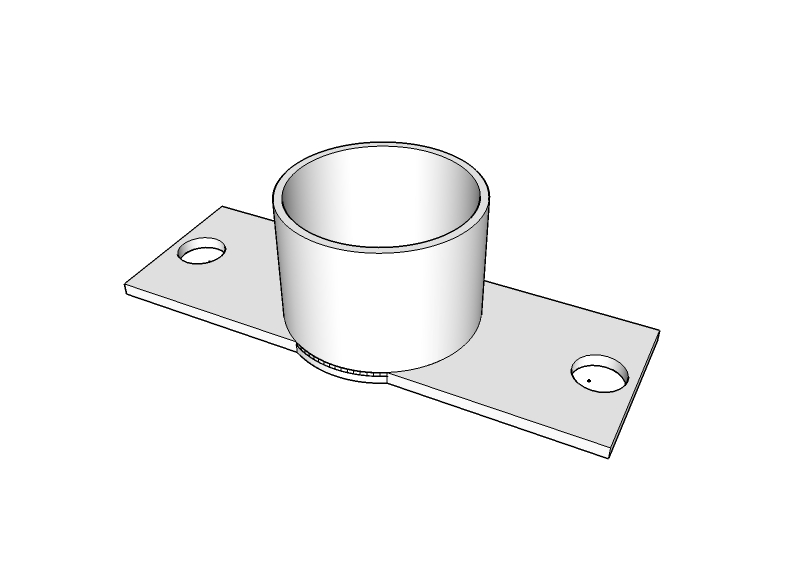
Here's the 3D model of the cam mount.
And the 3D printed one.
So I only placed the CCD straight int to miscroscope's beam without the eyepeice. It might seem weird but it's the most effective way I found, I've been doing this for years with DSLRs, taking of the lens and let the sensor takt the full blast.
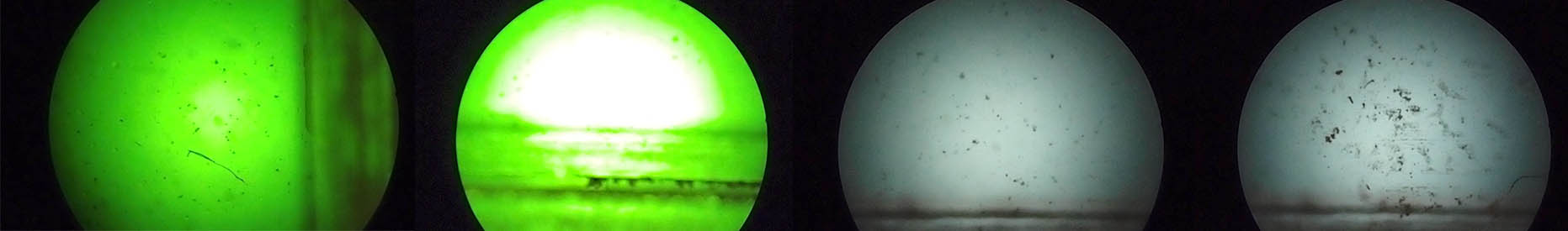
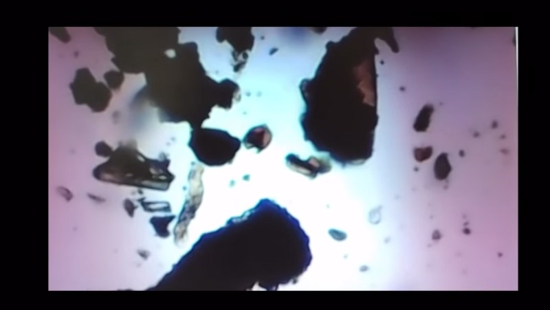
And here's what the webcam is seeing
And here's a video of me manually jogging the stage with a slide filled with dirt and water (and a worm swimming by really quickly at 1:04)
Arduino Code
The code is not that complex, It's a bunch of read write loops. with a Serial management part. If pot position is below where I have to go, set the proper direction pin to HIGH and PWM the Enable pin till my analogRead value is +-2 my destination (+-2 is to prevent pot noise). It can be set to check both condition a couple of time, if I'm not bellow and I'm not above, I'm +-2 to my destination so I do nothing anymore.
Here's the Arduino code
//Configure L293D direction/enable pins
//X
int xPlus = 2;
int xMinus = 3;
int xEnable = 5;
//Y
int yPlus = 8;
int yMinus = 7;
int yEnable = 6;
//Variables defining Motor Speed and Limits
int pwmX = 120; //130 best PWM value for both axises for smooth motion
int pwmY = 110; //140
int yPos = 300; //Position at startup
int xPos = 300;
int xminLimit = 160; //X and Y max and min analogue values
int xmaxLimit = 730;
int yminLimit = 230;
int ymaxLimit = 460;
void setup() {
Serial.begin(9600); //Init Serial Port
//Configure L293D pins as output
pinMode(xPlus, OUTPUT);
pinMode(xMinus, OUTPUT);
pinMode(xEnable, OUTPUT);
pinMode(yPlus, OUTPUT);
pinMode(yMinus, OUTPUT);
pinMode(yEnable, OUTPUT);
//Set the Serial timout to 50 millis so it waits only 50 millis for the Serial.readStringUntil() function
Serial.setTimeout(50);
}
void loop() {
//Check if there's serial data in the buffer and if so, extract the coordinates in xPos and yPos
while (Serial.available() > 0) {
char in = Serial.read();
if (in == 'x') {
String posX = Serial.readStringUntil('y');
String posY = Serial.readStringUntil('!');
xPos = constrain(posX.toInt(), xminLimit, xmaxLimit);
yPos = constrain(posY.toInt(), yminLimit, ymaxLimit);
}
//Move both axis
moveX(xPos);
moveY(yPos);
//Send new position back to the computer for validation...
Serial.print("x= ");
Serial.print(xPos);
Serial.print(" y= ");
Serial.println(yPos);
}
//This is to keep both axis in place.. It can be removed if between moves I want to move the axis manually
moveX(xPos);
moveY(yPos);
}
//MoveX and MoveY Functions
void moveX(int pos) {
for (int x = 0; x < 1; x++) { //This is the numer of time the loop is repeated.. the lighter the peice, the more try it takes to be perfectly aligned with desired position. Inertiaaa..
//While desired position is above present, move in this direction!
while (analogRead(0) < pos - 2) {
digitalWrite(xPlus, HIGH);
analogWrite(xEnable, pwmX);
}
digitalWrite(xEnable, LOW);
digitalWrite(xPlus, LOW);
//While desired position is below present, move in that direction!
while (analogRead(0) > pos + 2) {
digitalWrite(xMinus, HIGH);
analogWrite(xEnable, pwmX);
}
digitalWrite(xEnable, LOW);
digitalWrite(xMinus, LOW);
}
digitalWrite(xEnable, LOW); //Disable motor
}
void moveY(int pos) {
for (int x = 0; x < 1; x++) { //This is the numer of time the loop is repeated.. the lighter the peice, the more try it takes to be perfectly aligned with desired position. Inertiaaa..
//While desired position is below present, move in that direction!
while (analogRead(1) < pos - 2) {
digitalWrite(yPlus, HIGH);
analogWrite(yEnable, pwmY);
}
digitalWrite(yEnable, LOW);
digitalWrite(yPlus, LOW);
//While desired position is above present, move in this direction!
while (analogRead(1) > pos + 2) {
digitalWrite(yMinus, HIGH);
analogWrite(yEnable, pwmY);
}
digitalWrite(yEnable, LOW);
digitalWrite(yMinus, LOW);
}
digitalWrite(yEnable, LOW);
}
Processing Code
I wanted to make a processing sketch that would move the slide a couple of mm, take a picture and repeat until the whole slide is scanned. Using webcams with processing is really awesome. There's soo many things possible, it's juste a huge playground to explore. For this project I will only be using the webcam to save some pictures as the microscope stage move stuff around but in the future I'd be really interested in exploring motion tracking, logging and timelapses. The code is not really complex here either, send coordinates to the miscoscope stage through the serial port, take picture and move on. Everything now is in the tuning, how far should it move so I can merge the pictures with photoshop and how many can it do at a time.
//Import required libraries, it's all basic processing libraries
import processing.video.*;
import processing.serial.*;
//Init Cam and Serial Class
Capture cam;
Serial myPort;
//initial positions
int xPos=285;
int yPos=115;
//position increment value
int stp=2;
//XY limits for the scanning zone
int xminLimit=512;
int xmaxLimit=593;
int yminLimit=280;
int ymaxLimit=414;
int x=xminLimit;
int y=yminLimit;
void setup() {
//Init Serial port
println(Serial.list());
String portName = Serial.list()[1];
myPort = new Serial(this, portName, 9600);
//Set window size, 640x480 is my webcam's resolution.. pretty lo-rez :(
size(640, 480);
//This is the "Capture getting started" example I simply copy/pasted, it's really basic stuff
String[] cameras = Capture.list();
if (cameras == null) {
println("Failed to retrieve the list of available cameras, will try the default...");
cam = new Capture(this, 640, 480);
}
if (cameras.length == 0) {
println("There are no cameras available for capture.");
exit();
} else {
println("Available cameras:");
for (int i = 0; i < cameras.length; i++) {
println(cameras[i]);
}
cam = new Capture(this, cameras[1]); //My camera's proper config are stored in the second element in the array. [0] is 640x480 5fps.. [1] is 640x480 30fps.
cam.start();
}
}
void draw() {
//Send slide to initial coordinates
moveSlide(x, y);
//As I want feedback of what is happenning, instead of using 2 for loops, I incremment values every loops instead.
//This if() is making sure the first move, from initial position to scanning position gives enough time to the camera to
//turn on. 4 second delay.
if (x==xminLimit&&y==yminLimit)delay(4000);
delay(500);
//when there's an image available from the camera, read it
while (cam.available ()==true) {
cam.read();
}
//Draw image "cam" on the top left corner of the screen
image(cam, 0, 0);
//save screen as .jpg in sketch directory
saveFrame("SCAN########.jpg");
//increment position by the predefined "step" value
x+=stp;
//if x is beyond x maximum, goback to min and increment Y pos by step value
if (x>=xmaxLimit) {
x=xminLimit;
y+=stp;
//if Y pos is beyond maximum value, close program
if (y>=ymaxLimit)exit();
}
}
//the moveSlide() function sends coordinates through the serial port for the arduino to receive and handle
void moveSlide(int xp, int yp) {
//constrain keeps values from going off the grid
yp=constrain(yp, yminLimit, ymaxLimit);
xp=constrain(xp, xminLimit, xmaxLimit);
//since on the arduino side, serial data is handled as strings I'm converting my ints to strings and send them.
myPort.write('x');
myPort.write(str(xp));
myPort.write('y');
myPort.write(str(yp));
myPort.write('!');
delay(10);
}
Here's what it looks like when both programs are running together. I ended up with a couple of thousands of pictures.. I just need to find an easy way to merge all those pictures.. photoshop won't do it with that much pictures, maybe merging them by rows or sets of 4 could be possible. but I don't think handeling 2000 pictures is what they had in mind whe they made that photo merge function..
And here are the files generated....
Digital Fabrication Project Developpement
What tasks have been completed, and what tasks remain?
I've managed to build and program the arduino clone and managed to drive it using a processing sketch. Eventually I would love to push the processing side a bit more by implementing motion tracking, point of interest logging and find new samples that could be used to generate cool abstract videos.
What has worked?
Impressively, pretty much everything worked out pretty well, from using those motorized pots to my stage design. I was pretty sure the design would fail monumentally.. but it didn't.. it's behaving quite well, only a few hicups here and there since the groove is slightly too large for the slide.. it can rotate slightly sometimes and the sharp corners of the slides sticks in the acrylic.. a little push usually get it back on track though..
What hasn't?
The photo merge process I wanted to used to generate huge pictures of the whole slide can't handle that many pictures at a time, I would need to figure a way of only merging a few at a time. 2x2 grids, then merging those new images in 2x2 grids again untill I get everything merged.. I'm pretty sure I will figure a way to do this, maybe even in photoshop batch operations scripts. Preparing folders with processing first then send photoshop to investigate all those folders. That would be a pretty awesome thing to do, and really interesting to develop.
What questions need to be resolved?
How fast can it go?
What's the precision?
How many millimiter is a 1/1024 of an analogueRead on the slide pot...
What will happen when?
I was really impressed by the weird motion it generates when a slide with liquid is moved quickly over a couple of mms. A weird tide-like motion at a micro-scale, moving translucent worms and random debris around. I don't know exactly when I'll be messing with this newly found aspect of my device, but I know for sure there's something to be done there that could end up being pretty amazing. Seeing this, I've come to decide that motion tracking would have to wait a little longer.. plus... finding, clean, proper samples for motion tracking might be quite difficult. I've been collecting tardigrades and rotifers for a while but they usually come with lots of dirt.. Motion tracking might be hard when your tardigrade ends up crawling under a rock..
What have you learned?
I've learnt a lot about Adobe Premiere with this final project.. as I was so excited by every shot I got from the webcam. I also learned that I can use motorized slide potentiometers as actuators for micro movement. It's not ideal but really decent for my kind of projects.