WEEK 11 - Output Devices
Assignments: add an output device to a microcontroller board you've designed and program it to do something!
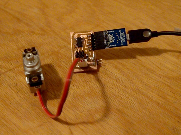
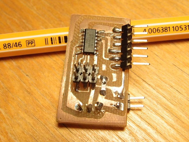
ServoController Board!
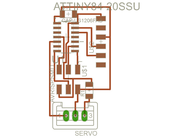
DESIGN FILES
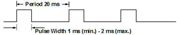
For this week's assignment I decided to make a board to control Servos via the Serial port using the attiny84. Controling a Servo isn't that complicated, it only requires good timing. 20ms cycles with pulses varying from 1ms to 2ms, 1ms being -90degrees and 2ms being 90degrees while 1.5ms is 0 degrees.
I wanted to mess around with this as I read that the Arduino servo library is not working on the attiny84.. I tried it and it's really not working as expected. So I designed a board, usual stuff now, a servo needs one pin and a connection to VCC and Ground, I used the serial port design from my other boards and an hour later messing with Eagle, I was ready to mill the pcb.
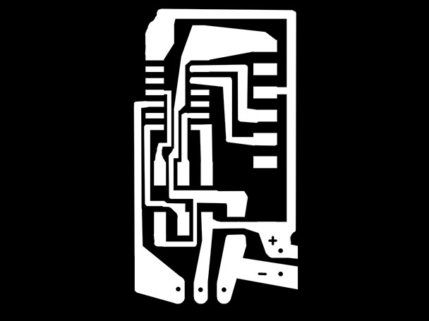
I forgot to take pictures of the process but it looks pretty much like every other board I milled.. and soldered.. set the PCB rig on the CNC table, surface it, change tool, tape copper plate to rig and press play. I always use the fabmodules to generate the toolpath now, setting the cut depth and material thickness to 0.01mm, tool size to 0.1mm with 5 offset pass with a 10% overpass. Setting my zero slightly above the copper plate, testing my toolpath, lowering the zero by a tinny amount till I get a decent trace. 10 minutes later, the board is ready for soldering. A dab of solder on the pad, hold component with tweezers re-heating that dab of solder so it sticks there then proceed with every other legs. I really enjoy soldering my freshly milled PCBs, it's really relaxing.
Programming with the Attiny84 with the Arduino IDE is pretty straight forward when it's properly configured.
I figured it out following these instrucions.
http://highlowtech.org/?p=1695
CODE HERE
Now I can send positions straight to the servo using the Serial port and everything is working pretty well. One byte at a time.