The assignment, much like the others, was simple. “design a 3D mold, machine it, and cast parts from it.” Attention needs to be given to the term “3D mold”. In order to fulfill the requirement, effort must be made to include compound shapes in the Z axis. A simple part could not just be extruded.
During the lecture, several times Neal warned to “not go deep”, or at least don’t go detailed if you do. Pay attention to this! This is sound advice. So what is “deep”? In my case, anything over 1.25 inches.
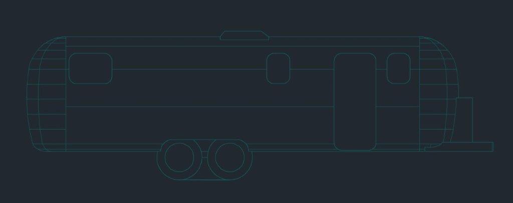
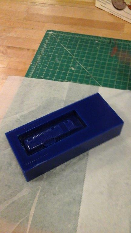
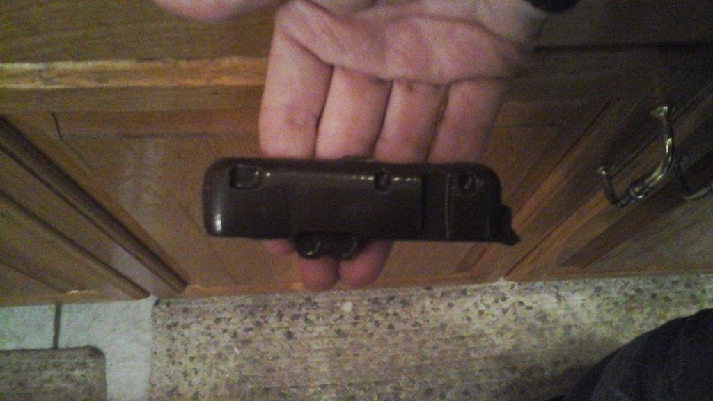
As suggested, I attempted to use this week’s assignment to gain progress on my final project. My project is a prototype 1/8 scale model pinball machine reproduction. I decided to attempt to cast the body and head of the machine.
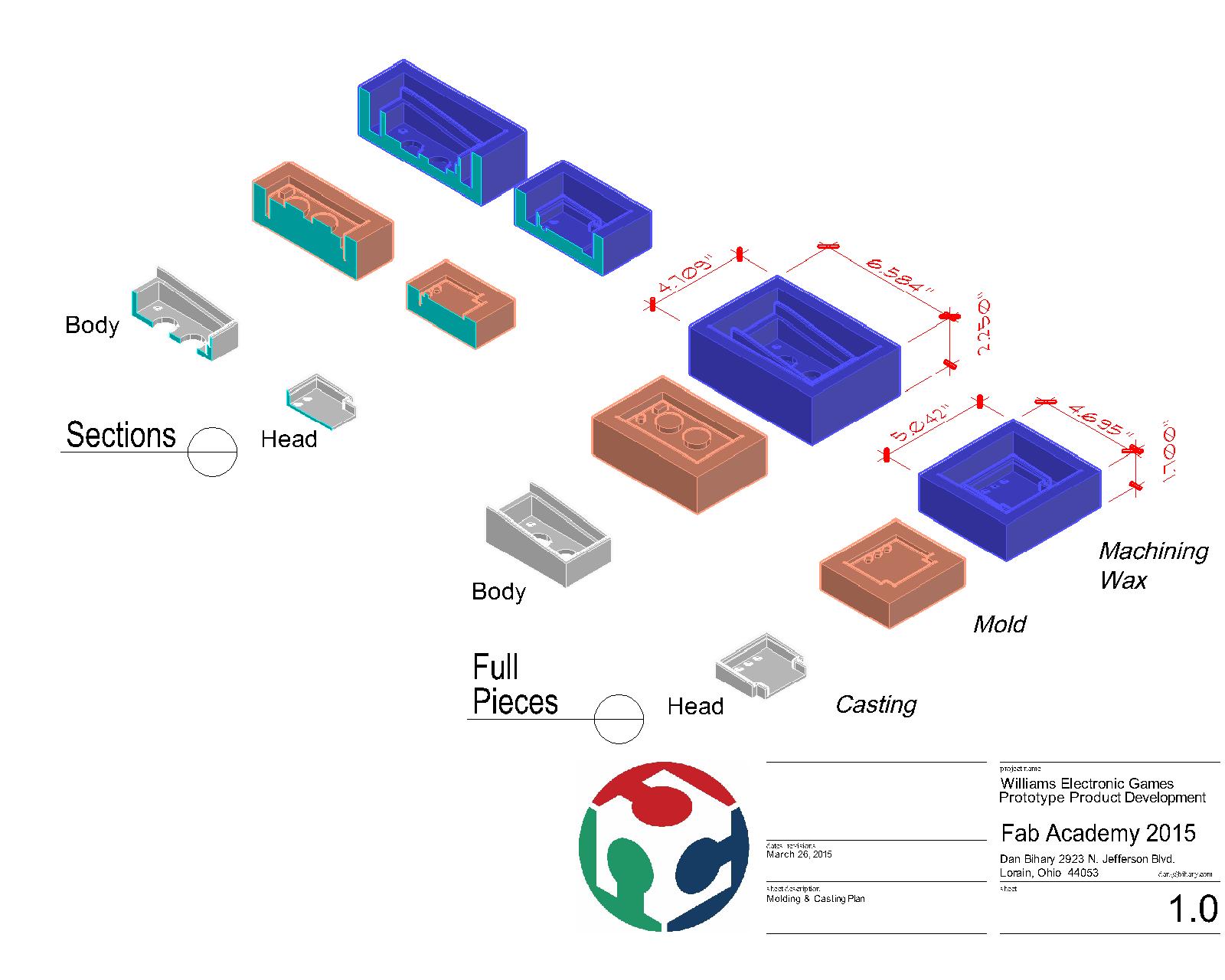
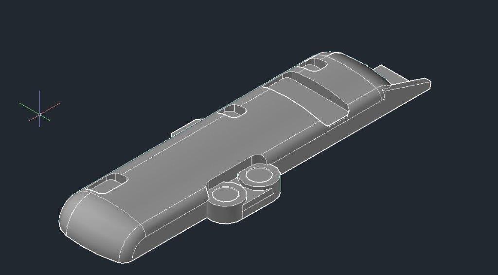
I already had the geometry created. The cabinet top is slanted at 7 degrees. This should meet the “3D” requirement. The body would require a machined area about 6”x4”x 1.75” deep. This would provide a challenge for the Shop Bot.
The AutoCAD data was brought into Solidworks and converted to a .STL file. This file was then imported into Aspire 4.0 to create 3 toolpaths. All toolpaths would use a 1/8” diameter flat end mill. A rough-cut was done first with a .003” offset. Two finishing passes were then done.
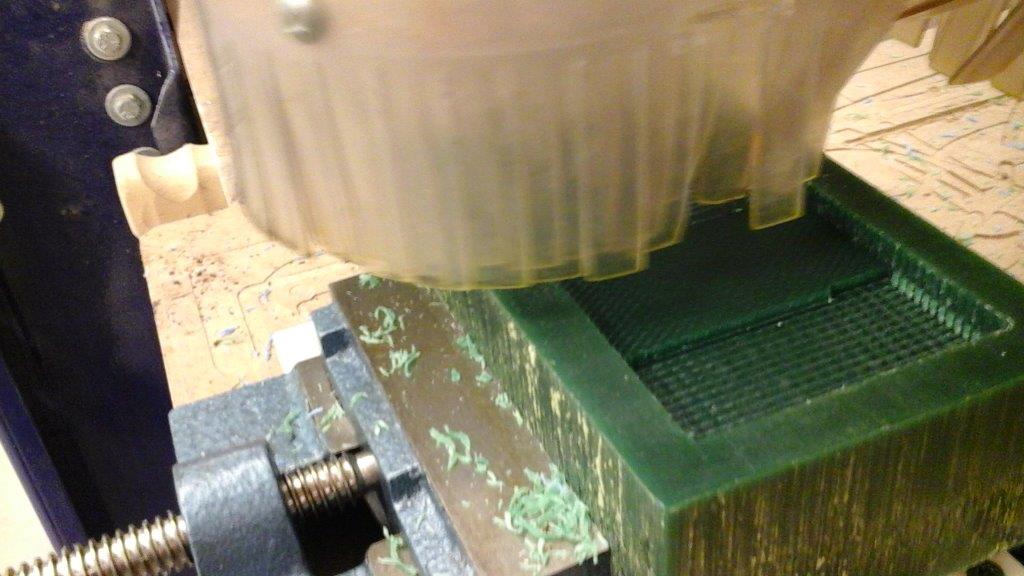
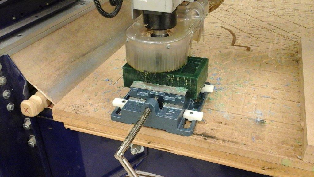
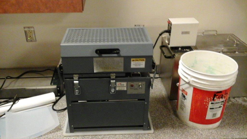
Aspire estimated the job to take about 80 minutes. Green machinable wax was clamped in a vice that has been screwed into the sacrificial table of the shop bot. the long axis was made to be the Y. The bit was chucked into the machine with just enough exposed to make the maximum cut depth of 1.75 inches. Our Shop Bot has an automated routine to zero the Z access. The first step of this process causes the bit to move to 5,5. As that would put the bit away from the wax, a new origin would need saved. The new origin would be set to -2.5,-2.5. This allowed for the routine to put the bit over the wax. The Z was correctly zeroed. Now the bit was returned to 0,0 and the XY was reset.
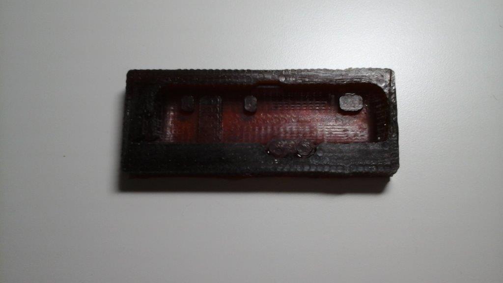
The cut was started and proceeded well for about 30 minutes. The bit stepped it’s way down, but the path was very inefficient. Aspire directed the tool to make very short passes in between the walls that consumed a lot of time. With only a couple of minutes to go in the rough cut, the bit picked up a shaving a “weed whipped” it into a wall and broke off a piece. This could be repaired, so I continued with the cut.
The rough cut finished and the first finishing cut immediately started. After about two minutes, the bit became bound in the deep cavity of the wax and broke off. As the mold was damaged, I elected to stop the process and scrap the mold.
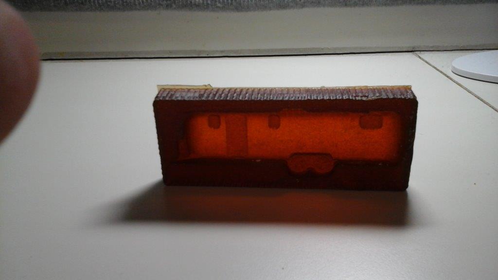
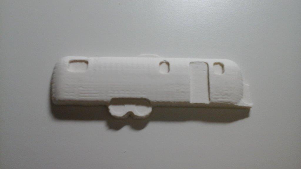
After regrouping my thoughts, I elected to attempt to machine the head piece. I already had generated the tool paths with Aspire. I clamped a new block of wax on the Shop Bot and started the operation.
This cut should be much easier as the maximum depth was only about one inch. The job was supposed to be about 20 minutes. The rough cut proceeded without incident, although some unexpected plunges took place in the corners. I then ran the finish cut. Unfortunately, the rough cut had failed to remove a significant piece of wax in a cavity. The bit hit this wax and broke. This process was also aborted. In studying why I was having these problems, I determined that the biggest factor in the failures was the inefficentcies and errors in creating toolpaths from .STL files. If I were to attempt these projects again, I believe I would import a 2D drawing into Aspire and recreate the part internally. This would provide much better control of the cutting process. As much as I wanted to use this week’s assignment to help complete my final project, it just was not suitable. The deep flat surface with thin walls pushed beyond the practical limits of the Shop Bot. Although I’m sure it could be completed, my attempts just was not the best method.