This week assignement was to add an output device to a microcontroller board you've designed and program it to do something
*All files provided on the navigation menu.
Meta, i think this is the idea of this project, at least when it comes to matrix logic, i used a matrix logic for the input and a matrix logic for the output. In the input (Input week 12) i used to control a matrix of switches (16). And in this week i started to study another matrix as an output for the Leds, and an input for the drawers for the final project (link). For now i was able to implement just the Output part of the Led Matrix on the final project, but i'm confident that the input part will be something i can assign on the software later on.
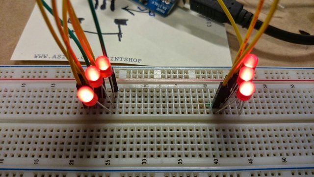
To beggin i started using a breding board and some leds, to check three things: one if the pins can light the led bright enough, two if i could modulate (PWM) the pins for all leds to make them bright enough and at the same time possibilate more leds be lith at the same time with less current (knowing that the microcontroller has a limited current that it can output) and three if i could use the leds as an output and an input, meaning when the led is bright and when i remove it from the bread board the microcontroler can see that i has been removed, that serves me to check if the drawer is open or closed. And all worked in the breadborad and usign the serial out on my board used to test the keypad matrix (see design week 08).
Flikering Leds till the human eye don't notice them
Test the delay of the Leds
Testing the serial communication with the Led
Than i started to think in the fisical conections of the Led matrix and the led with the drawers. The fisrt test worked but the led stiked to far out, so i putted it inside the drawer and made a small hole so it could be more discreet and better secured in place (i made another hole on the bottom so the leads of the led could be bent and making contact with the copper on the structure. It all worked with two problems: one the wires got cought when you opened or closed the drawers, so i had to thing of a way to remove the wires from the way that the drawers moved, two because the plastic drawer was to light it didn't always made a good conection with the copper tape.(there is a cooper tape on the bottom of the drawer and another on the structure, so they can make fisical contact), i resolved that putting a blob of solder on one structure side of the conection, because doing this any imperfection on the straightness of the drawer or the structure can be fixed and it is on the end of the structure because the structure ends on the middle of the drawers and that makes the drawer act like a (gangorra), if i placed the copper on the front of the structure when the drawer had more height on the back than the front, the front would go up and not conect with the copper. I also calculated each led to be the maximum bright under 5v power, and for that i used a ???ohm resistor, and i soldered direct on the cathode making a seamles new lead for the leds.

Back (first test), wires got stuck

Test with two Leds, one already inside the drawer another outside

Back (second test), using wires not cables and straight lines, much better

Testing the conection of the Led and the copper connectors, and it worked

The Led calculator, minimum resistor for maximum brightness

And led with a 100ohm resistorm calculated for 5v

Bending the leads of the led an the two holes to fix it

Testing what is the minimum aperture a drawer can have to be considered open/closed

Testing what is the minimum aperture a drawer can have to be considered open/closed, now with the led
Testing the connection of the Led and the copper connectors
Straighting the wire, see wire not cable, for this to work it has to be a solid wire or even a (arame). The first thing you do is get two pliers, or in this case a plier and a vice, and recure one end in the vice/plier (always the metal part, not the insolation) that in the other end you secure the plier and twist pulling it at the same time, and after a couple of twists it will be straight, for more hard wires you can use on the other side a eletric screw driver.

Straighning the wire, securing on vice

Straighning the wire, pulling ans twisting

Straighning the wire, ready

Cutting the copper tape on the vinyl cutter, simple cuts to waist less material

The solder blob

The straight wire rows and columns
The last part was to undestand how many pins i could use for the matrix, i knew i nedded at least 8, but i also wanted to put the matrix in the i2C network, so i had to figured it out if i would use the Attiny45, 84 or the AtMEGA328. In the end i found out that the 84 is perfect for up to a 5x4 matrix, leaving 2 pins for the i2C network and Power, Ground and Reset reserved (14 pins total), if i needed more pins i could use the AtMEGA328p, that gives me, excluding i2C(TWI), power, ground, reset conections, 20 i/o free pins. So i started to design the board on Eagle and found out that the only thing that was sticking out was the SPI header, so i made a breakout board just for the SPI and FTDI header (if i nedded to debbug something about the code). It is a simple breakout board with two wires that goes to Reset and MISO (MISO is later reused as an i/o pin). And so i end up with a very tiny, very flat and very simple board, that can control my drawers led and in the future (hopefully) the open/close status of them. PS: In the future i hope to eliminate all conectors because i found out ind the Application and Implication week (17) that they cost a lot in relation to the low cost of all the other components on the system.

Undestanding how many pins to use on the Attiny84a

Using the SPS programer as a breakout board with the FTDI and SPI header

Checking how much current all the leds take, 0.46A

Yes! A lot of work and it works!!The happiness of seeing a bunch of leds light
The Speaker is just a 8ohm speaker connected to the SPS Masterboard (ATmega328p), on a pin with a 100ohm resitor. I had test the code and the speaker already on the Embedded Programming week (09) but one limitation on the Attiny is that the code for that dosen't enable a lot of sounds (at least not the code i had) and the code for the AtMEGA328 is the same as the Arduino board code, so it is much more complete and allows a lot of sounds and has a lot of tutorials online, so i decided to put the speaker in my SPS Master board because it had some free i/o pins. And i worked without a problem using the Tone library and the Arduino IDE.
For the LCD i made a breakout board, or as Adafruit calls a backpack for my LCD, and i'm so proud of how it came out, becayse is something i'm sure anyother student of the FabAcademy cand use.
I started to think in using a mini display we had in the Lab (SSD 1306 128x64 Oled), a i2C dislpay that used the U8glifd Library and can display a lot of diferent and complex forms and shapes, so i hooked it up in a breadbord using the SPS Master board to drive it, all it all worked fine (i was using the 1k ohm on the i2C line,later i discovered that for my application is best to use de 499K, but for the display it worked fine).

The i2C mini Display (SSD 1306 128x64 Oled)
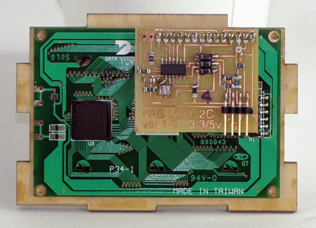
But after some time, and when most of my parts wore working by themself (parts of the final project) I raise to the challenge to make another display (Datavision DV-16400-S1FBLY/R22, datasheet on the files section) working with i2C, it's similiar to the inventory LCD display but it has 16x4 character and not 16x2. So the first thing i did was to connect via a breadboard, to see if it would work, and it didn't, what happened is that i forgot to use the resistors for the i2C data lines (it was my first i2C project other than the the plugin Oled display) after i put the resistors in place it didn't work too, because i was tired and the breadboard had a lot of wires i plugged some wrong, so i gave up and the next day i plugged everything in the right place, and again nothing, so after reading a lot and finding the datasheet (was not easy task) i found out that the display comes in 3.3v and 5v, mine was 5v but i was using 3.3v, so i plugged everything wright and hopped for the best, and it worked, after everything was working and reaserching for some similar backpacks i found out they all use a potenciometer (dimmer) for the display. So in the end i had a lot of things to put on my Eagle design to improve even the Hello.LCD board that Neil did on the Output devices week. A 5v and 3.3v regulator (to be chossen), resistors on the i2C line and a potenciometer. I used for inspiration Neil's Hello.LCD board the JeeLabs lcd-plug, the ADAFRUIT i2c / SPI character LCD backpack and the SparkFun Graphic LCD Serial Backpack. In the end i forgot the to mesure the fixing holes position and tried to "edit" the board but broke it, then i redesigned and remade the board, but it fell on the ground and broke the pins (but i was not happy with that because the headers stick up). So in the end i used a final board design with flat header for the i2C and for the SPI header i would suggest to solder the header in place an then remove or just put the pads there and conect the cable with header via pressure, just when programming the board. And to finalize the code is preaty simple, using the TinyWire Library and the LiquidCrystal or LiquidCrystalFast Library (on the files section). The only difference is that for the 4x16 display the Fast Library fix a bug that can be fixed by writing the line you whant before the text on that line (like on my code), the bug is that the Library thinks the 4x16 is a 2x16 display so when it prints the characteres prints the lines in this order, first line01, than line03, than line02, than line04.

Hello World! on the LCD display via i2C

Testing the potenciometer

Opsss... broke the board

New board

New board stuffed...

And working

And broke
And the final one, new and improved
I had already used a speaker with an Hello board (ATtiny84a) that you can see in the (week), but it was a little complicated and the range of possibilities for the sound in that board is limited (because there is no "round" librarie for that). So since i had pins there wore not being used in the SPS Master board, and it has an AtMEGA328p (that carries the same library as the Arduino board) i made a connection for the speaker in that board and it worked fine uploding the program with the Arduino IDE, the only thing i had to modify in the 8ohm Speaker was the cable that was to short, for that i solder the two cables and isolated them with a heat shirnk tube (very practical and very professional).
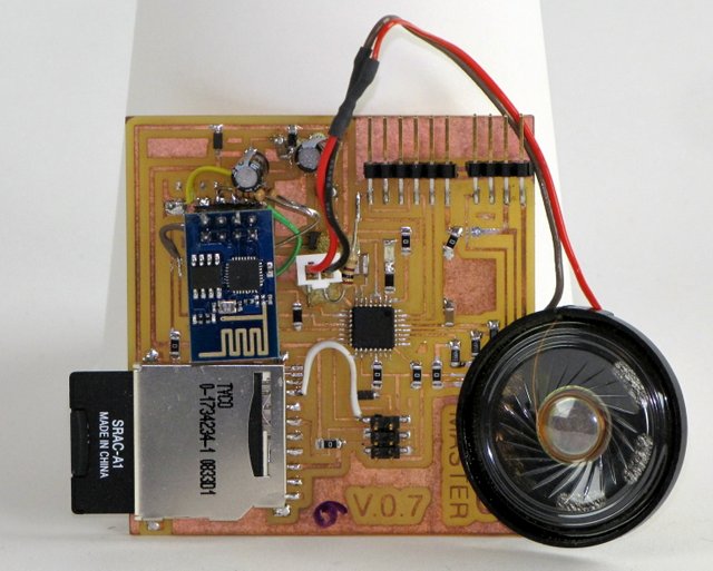
The SPS Master Board with the speaker
I guess it works for both, but for my project i will use mostly as an output, to put data as a backup before sending via the Wi-fi board to the internet. (note that this is not yet implemented in the Final Project, but it works and i will be using in the Application assignment).
For this assignment i used the Adafruit Wave audio shield for Arduindo as inspiration to see what pins i needed to connect to what, the only difference is that i used a 3.3v Zener Diode insted of the Level Shifter (link mouser) to bring the logic of the atMEGA 328 from 5v to 3.3v. Everything worked with no problem usign the SD library and the Arduino IDE, and also using the FTDI header (and cable) to acess the information from the SD card to the computer. (the Wave Shield Schematic and

The SPS Master board with the SD reader part