This week assignement was to design and build a wired and/or wireless network connecting at least two processors
*All files provided on the navigation menu.
For this exercise Shawn proposed we did a common board, different from the SPI Hello exemples, this made sense since to talk to the internet seems more usefull (or at least more innovative) than to just talk to other boards. It was maybe the first really difficult exercise of building a board from the top down on Eagle and even to try to understand what all the resistors, capacitors, regulatores, etc. are for.
And for this exercise i decided to go complicate even more and try to make my central board for my final project (because i already had a board to control the led matrix and another to input the buttons, not the final board but a proof of concept). I will not explain the entire board, but just so the photos are compreensible, it is a board with and AtMega328p, with a i2C and FTDI header, an SD card reader an LED and a output for the spearker. And yes in the end i had to do many ajusts (i guess that's why people start putting versions printed on the boards).
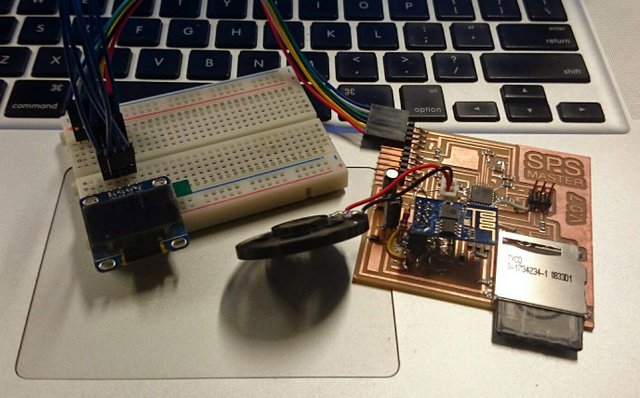
The complete SPS MASTER board with perifericals (LCD, SD, Speaker and Wi-fi)
So i started to create the schematic on Eagle, and putting all the parts and research for the connections and ways of the parts i didn't know how to connect, and because i wanted a flat board (don't know why)i choose to use not the ESP 8266 that everyone on AS220 was using but a module that can be soldered as SMD dirrectly in the board, the ?M-06?. In the end because it's a new module and documentation is not good on that it didn't work (a lot of tests and debbunging and nothing), one thing that is difficult is that board don't have any Led to guess if it is working (and belive me, hardware output as a motor turning a sound ou a light from the board is very, very important for debbuging).
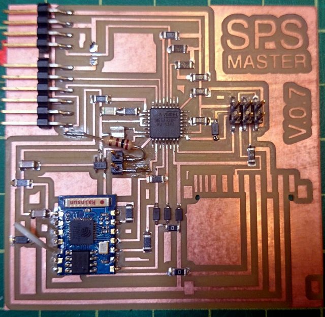
Trying t use the M-06 wifi module
In the end i just used the ESP 8266 module, but also didn't work, the problem is the board worked, the bootloader (fuses) wore correct burned by the Arduino IDE, but the example skecht didn't work (on the files) but the red Led on the board was lithing, so we put a lot of commands on the skecht to debbug the problem, for that we putted a lot of print to serial commands, on every step of the program, and what we saw (other people wore having the same problems) was that the board was continuasly reseting, so i thought it was a energy problem and tryed to put big capacitor on the input an output on the regulator (i was usign a regulator from 5 to 3.3v because the ESP8266 and the SD reader bouth work at 3.3) and that made it, the module works perfectly, and one thing that i discovered is that the module is not very strong comparing to other devices, so when we wore all (10 persons) working on the AS220 FabLab with all computers connected to the internet the module was not abble to connect, but in the next day when almost nobody was there, didn't have any problem.
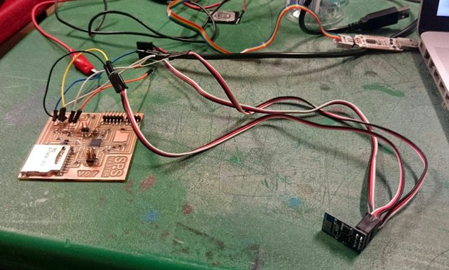
Prototipng with the ESP8266 module
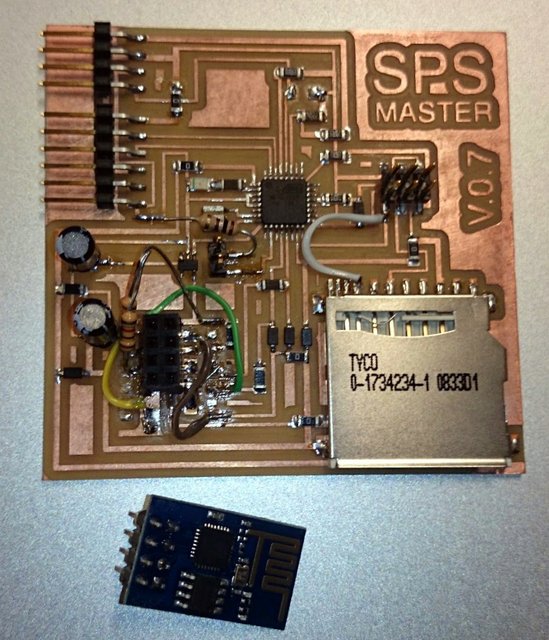
The final cirgury on the board to work with the ESP8266 (header and capacitors)
The second part of this assigment come to life when i finished to make all the boards and hardware for my final project, because i project all the boards to communicate whith each other via i2C protocol, the ideia behind it was to use the least amount of i/o pins in the Attiny84, and for that i2C is perfect, it uses just to pins (SDA and SCL) and VCC and GND. For the beginner: VCC is power, GND ground, SDA is the Data line and SCL is the Clock line (for syncronous communication).
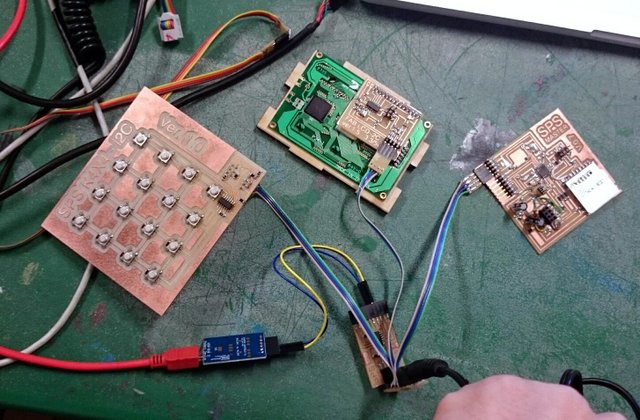
My microprocessor network, with 3 Attiny84a boards and one AtMega328p
There is an excellent explanation for why i2C (inter in communication) and TWI (two wire interface) are exactly the same, and it cames from a book: ".............." akdjaokdja book.
What i never had put much tought is how it would be difficult to do that, to make all 4 board to communicate with each other. And the reason for that is me, ok i have to addimit i have been using the Arduino IDE and its libraries and don't know how to program a board in any other way, and the problem for the microcontroler i was using (Attiny 84a) is that the library for that is not polished at all, and what heapens is you have to search the internet and figured it out what library goes well with each board, and sometimes modify that library a bit.
For this assigment i will show how i did a i2C network with the boards, and used a scannear program to prove it. But for the final project i will have to figure how to make the Keypad talk to the LCD display, it talk to the Master board and the Master talk to the Drawers board. A complete and complicated system for somebody that never program anything.
First a lot of research, and after some connections i did wrong (i putted the mandatory pulled up resistor in line with the SDA and SCL).
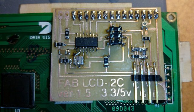
The LCD board with the 10K pullup resistors for the i2C
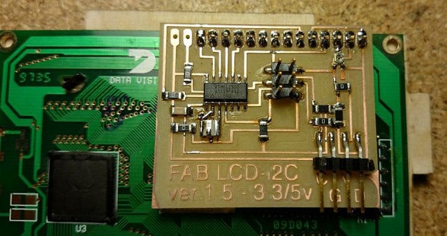
Swapped for the 4.99K resistor and now everything works on the correct clock
  Basic details of i2C communication:

- Transfer rate: 10 Kb/s (low speed) - 100Kb/s (relly on the pullup resistor)
- 128 possible addresses
- 16 reserved addresses
- 112 max devices
- Devices have to share both 5V (Power) and GND (Ground)
The i2C protocol uses a 7-bit address (there is even a newer version for 10-bit adress) for the slave devices. For my project that means 128 - 16 (reserved) positions = 112 - 3 ( mains system boards) = 109 x (5x4)(free pins on the Attiny84A) = 2180 drawers or 109 x (10x10) (free pins on the AtMega328p)= 10900 drawers.
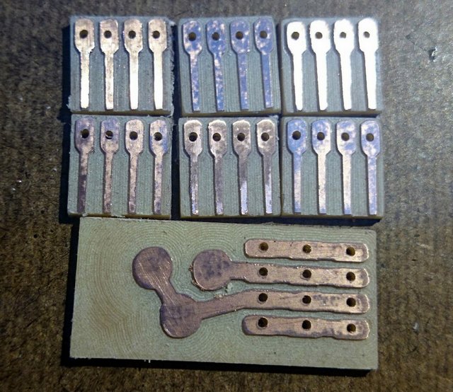
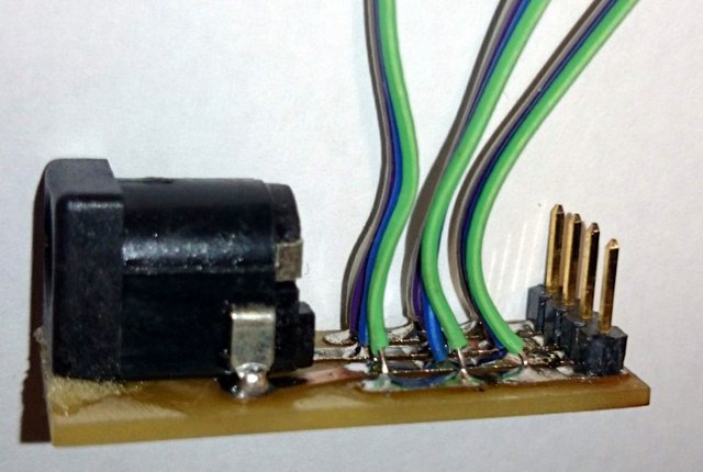
Made some boards for making the wire connection easyer
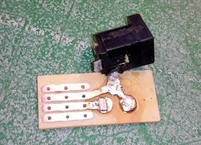
This is a power board for the i2C that connects all the board inside the main case
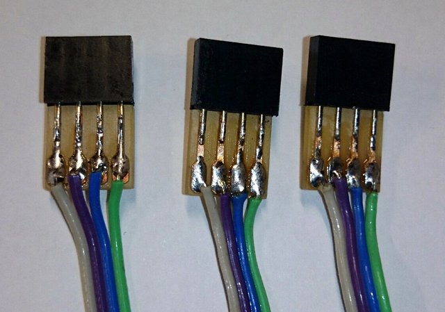
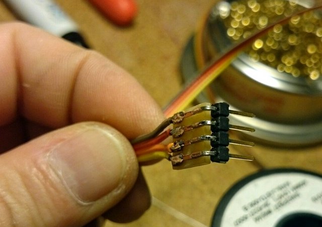
This are the i2C connectors ready, SDA, VCC, GND, SCL
The connector for the drawers
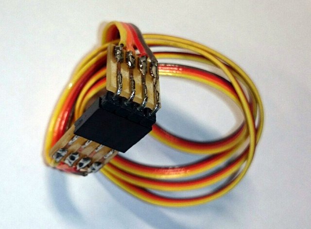
A liittle 90 degres conector
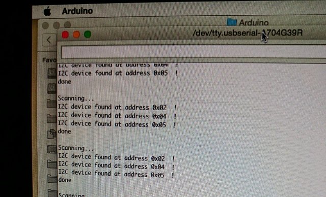
The Arduino IDE serial monitor showing all the board connected in i2C
And to finalize made a button send a byte do the LCD board and then printed the line "is this working?"