This week assignement was to measure something: add a sensor to a microcontroller board that you've designed and read it
*All files provided on the navigation menu.
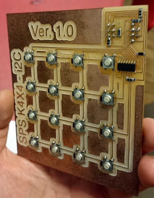
For this week i upgraded my 3x3 keypad that i made on the eletronic design week 08.(For my final project) The only difference is: that i included on the board the microcontroler (Attiny84a) and the i2C header. And the most difficult part was the design part in Eagle. Because i was interfacing the button board with real keys and a case, i had to figured it out how to make the design of the board in Eagle mach the design of the case and the design of the molded keys.
The test on the 3x3 Keypad using the Arduino IDE library
So the first thing i did was to mold the keys, 16 of them (for that you can see the molding and casting week11). Then i made the design for the case in Rhinoceros, modified in Autocad and cutted on the Epilog laser cutter. (See computer controled cutting week 05 to see more). Actually i designed the cover for the keys and the board at the same time trying to find a common denominator for both, using Eagle and Rhinoceros. So i had the idea to use 16 button (1,2,3,4,5,6,7,8,9,0,+,-,Ok,Esc,:) and P, then i divided a 4x4 uneven grid (20mm spacing horizontal and 18mm spacing vertical) on Rhinoceros, annoted the coordenates of each intersection point, than in Eagle in the "Properties" dialog box of each 6mm Switch i completed the expected "Position" dialog (this because the center is the point of origin of the Eagle part).
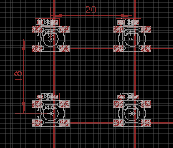
The 18x20mm "grid" on Eagle, the grid is with 0.4mm spacing (the diameter of the 1/32 endmill)
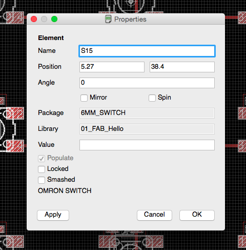
The Properties panel on Eagle
In the end another problem was because i am using the free version of Eagle it has a limited size board you can make so i almost could not fit all the traces, microcontroler and components on the board, but then i found out that Eagle size limiting is less on the horizontal part than is on the vertical, so i just rotate all the board and could work from there on.Once i finallized my board and tryed to program it i found out that i put 10k pull up resistor of Reset in line with the pin and not pulled up to VCC, so i had to make a littel modification, but in the end it all worked. For some curiosities about the design, the diode and the switches are so close to allow they fit insite the key area of actuation and to allow the board to be flush with the cover. And the i2C and the SPI header are in the other side of the board for the some reason.
On the week we wore milling the board fore some reason all our 1/32 endmills broke, so we tryed to mill some boards with the less broken endmills, and it worked, the only thing is when the milling end you have a lot of bur, so you have to remove that shaving (carefully) with another board and then use a sandpaper do end the job (i used a 1.000 grain sandpaper).
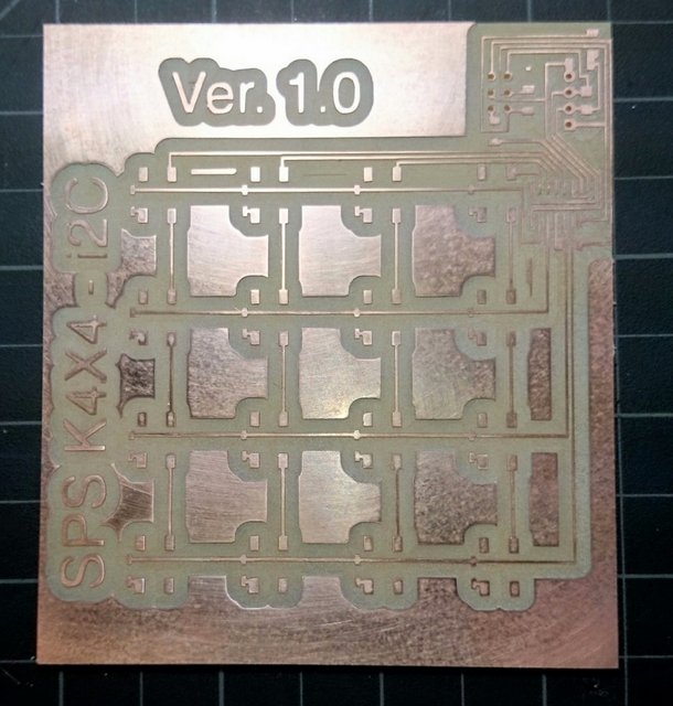
The 4x4 board, milled with a broken 1/32 endmill
The 10k pullup resitor fix! With a Zero ohm resitor
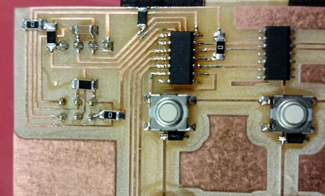
The stuffed board
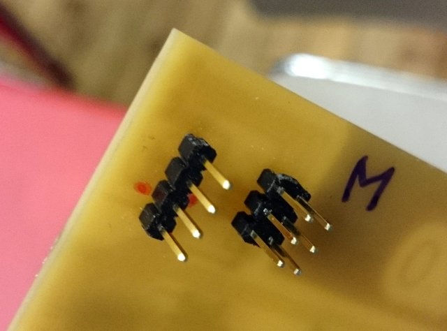
The i2C and SPI connectors on the back of the board
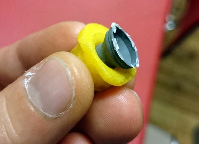
One Key and the rubber spring attached to it
In relation to coding it was really easy once i had already prototype with the 3x3 Keypad (eletronic design week 08), using the Arduiono IDE i uploded the Keypad Library and then applied the i2C WireTiny Library (a library for the Attiny microcontrolers), you can see a more detailed approach to that in the (Networkign week 15). I had just one problem because for the library i used i was supposed to put the rows where the columns are and vice-versa and because i'm nwe to coding and i didn't whant to change the library i just assigned the right code to the key, and the layout of the code is a little strange for that, but to check the working code it is the files section.(the code is fitted to be used on a Attiny84 with a internal 8Mhz clock).