This week assignment was to redraw the echo hello-world board add (at least) a button and an LED (with current-limiting resistor)check the design rules, and make it.
I made three boards this week! It was a productive week! For me and the final project!
*All files provided on the navigation menu.
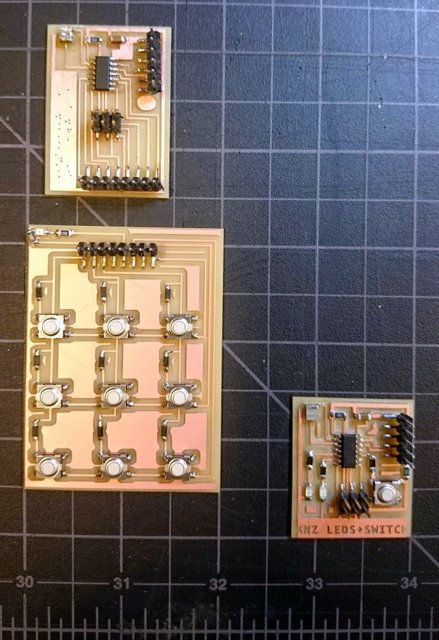
Three boards: Matrix 3x3 Keypad+Hellokey and Hello World!
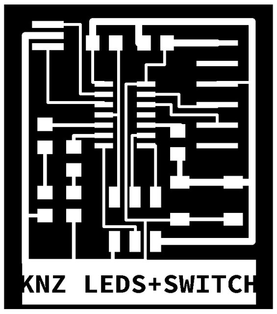
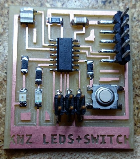
So actually i did this board last, but its a good board, with 2 leds and a button. After that i convinced Lara and Matthew to put three Leds on their boards!
First we got a lecture by Shawn and Ladia, a little complex but i am beginning to understand more and more about eletronics and programs. Also we had an introduction to the Eagle software.
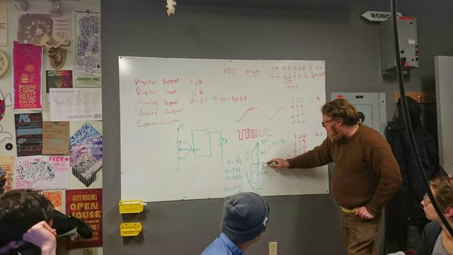
Shawn trying to explain why the circuit always ends in zero. Left from right: Simon, Avy and Jenny.
So actually this is my third board on Eagle and in the beggining i HATED eagle, but now i'm more confortable with it. Guess if you are in FabAcademy you have to learn at least one totally different software per week!
Now i would put all the parts isolated from one another in the schematic view. To much noise...
I started to do the boards with all the traces the same width but figgured it out that for some traces they NEED to be thinner and others can be thicker. (more on this on the HelloKey board)
The PNG file with diffent width traces and a big ground. (don't use this file it is wrong!)
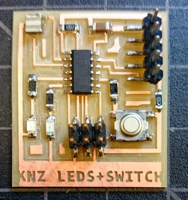
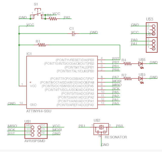
Complete board! Ok two resistor on the button because i screw the design!. Ow and a 5 pin header...
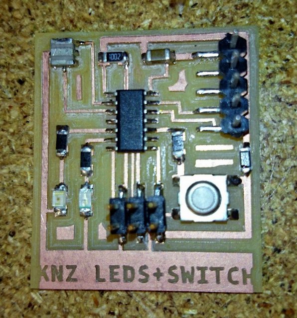
So i plugged my board in the computer with the TLL cable and the ISP programmer and from time to time the computer gave my a message "the USB device drawing too much power has been disabled", but other than that everything worked fine. I could program with diffent programs and the leds flashed okay. So after i show my board to Shawn he figgured out that i had a shortcut on the button, here is how i fixed it:
You can see that if you push the button the VCC goes direct to Ground without a resistor! No good!
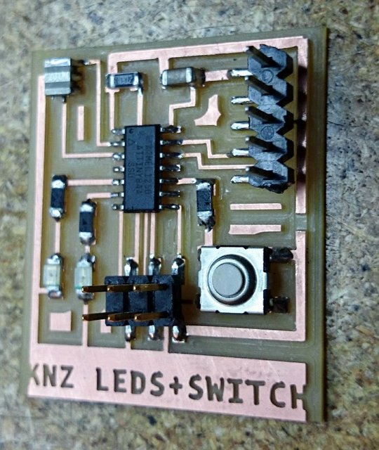
So with an Xacto knife i cutted a little piece of the copper...
And solder a 1K resistor on that trace!
And there you go a board with two leds (green and red) that i can control with the button. All the programming was made on Arduino enviroment (software?).
A gif explainig the use. This gif was not easy to make, but it worked fine!
So i began using Eagle because i wanted to test a theory: that i could make a keypad and not buy one. I read a lot of tutorials online on Keyboards and Keypads. And i stick with one with 3x3 Matrix. I used the diodes too because i don't what to have "ghost" keys when somebody press multiple keys! I made one because i could not figgured it out how they where able to do a matrix without crossing the columns with the rows, in the end is simple just use a component as a bridge. (is that the correct therm?)
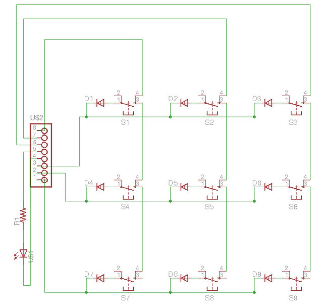
Eagle file, i used a 8 pin header but only needed 6 pins, so i put a Led on the remaining pins! It's always nice to have an Led!
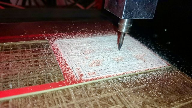
Cutting the board. That bed is old.....
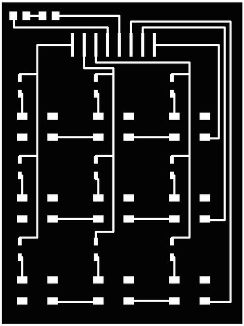
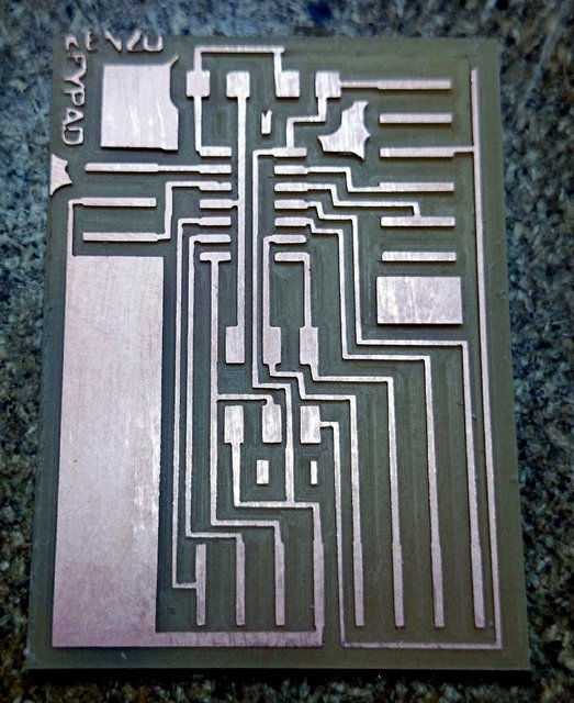
The PNG. file. I figgured out the how to make bridges using the buttons!
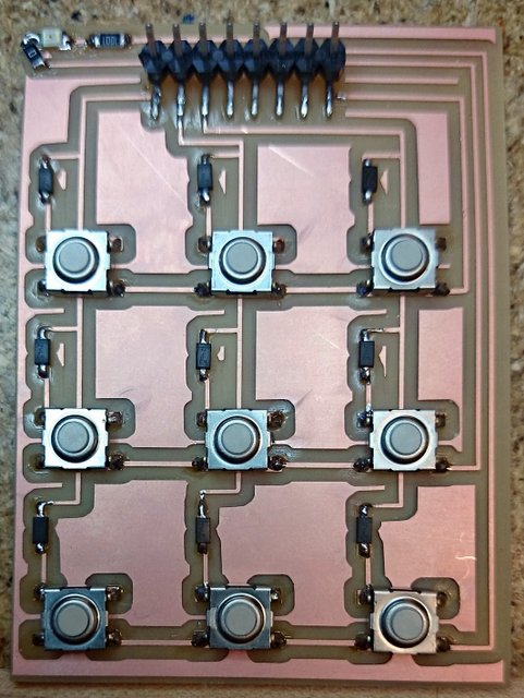
My beautiful board!Ok i forgot one small trace on the Led, but i fixed with a zero Ohm resistor!
I tested my keypad with the Arduino Uno board, and it worked fine. Ok first i have to say that i never used an Arduino before, so i had to learn about the programs and libraries (that took a couple of das)... but in the end it worked. Now i can see, on the serial monitor, every time i press a key on the Keypad.
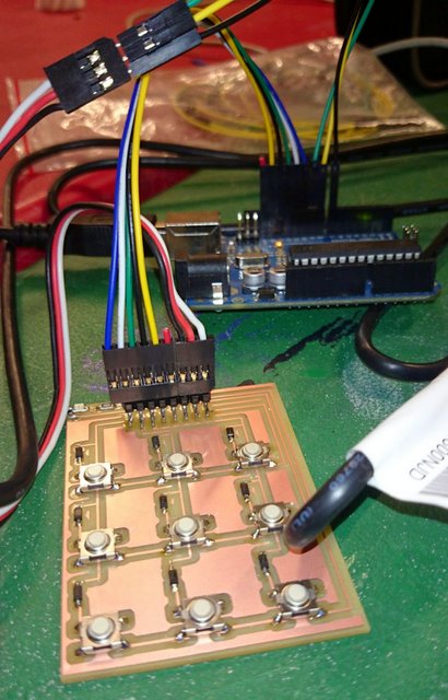
Testing with an arduino first! It worked fine!
So i got the Keypad working with the Arduino board, now i wanted to make a board with the attiny 84a, so i don't need to use the Arduino, though because we only had 4 pins open, so i researched and found out i can use the programer pins to!
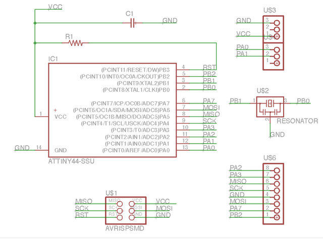
Eagle file, clean...
Ok now i have 8 pins that i need i just need to trace on the board, i was not easy but i got away with no zero Ohms bridge!
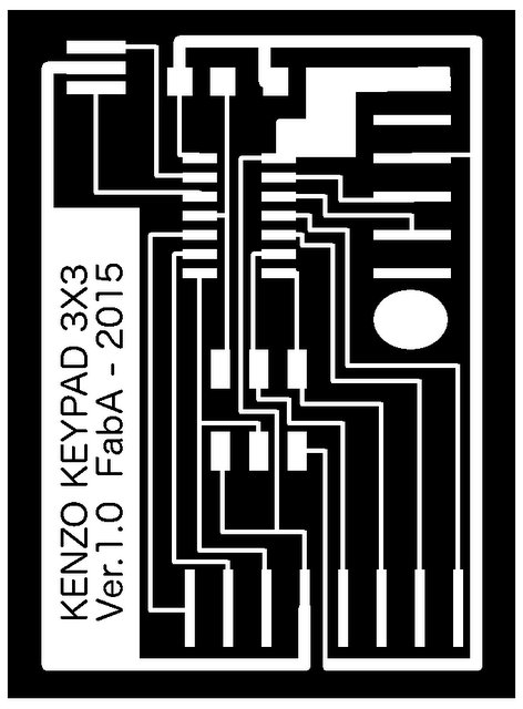
The PNG. for the board, the text was to thin and the Modela was not abble to mill them with the 1/64 mill (0.375mm).
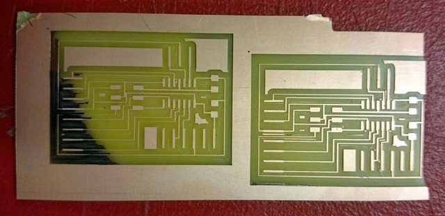
Tried to mill two boards but the bed was not levelled, got some beautiful mirror finish though.
Tried a third time to mill the board and it worked but the mill was so deep and the border traces so thin that they broke once i clean the board. (on the top of the board)
After that i took and entire day to shave a new bed for the Modela! (see process on the botton of the page)
Third try. Broke the traces after cleaning.
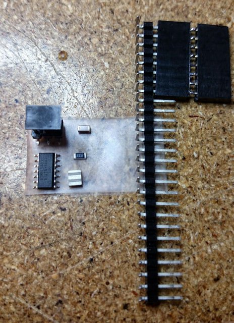
Components to solder, very few.
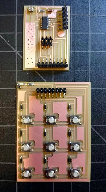
The two boards! Now just need to connect them!
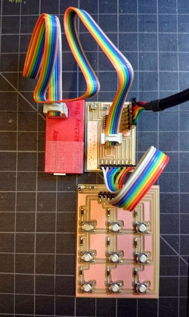
Made a new cable to connect the boards!
Ok, now i got the Keypad, the Hellokey board the ISP. So i figgured out that i could just flash the program, that i modified on Arduino Software, with the correct pins and everything would work. Wrong! Because i could not get the "serial monitor" to work. So more research and i found out that you have to install drivers for the FTDI (TTL to USB) cable to work and a library! So i did that and everything worked. I seams easy but i took me several hours on this process... Write code, compile, error, re-write the code, error, re-write, compile, error, compile, ok, flash, board dosen't work and so on...
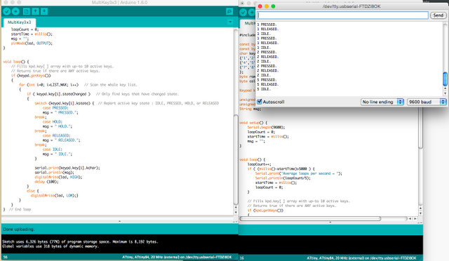
And here is the Arduino program runing with the three examples from the keyboard library! The Keys have 4 states: Pressed, Hold, Released, Idle.
The intersting thing about this assigment is to see a bunch of adults happy beacuse of a Blinking Light!!!
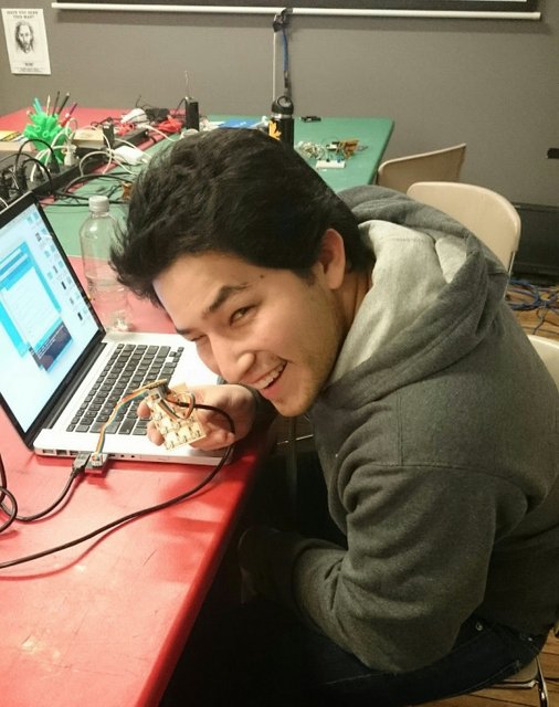
Happy! Because it blinks!
I got so much error because the bed was not even and Jill lost one board because it wasn't sticking on the bed. So i decided to shave a new bed made off masonite (compact wood fiber hardboard). Cutted the masonite on the Epilog laser (205mm x 155mm). Got my PNG. file the size of the bed (black inside with a white border, 20px). Put a 1/8 (3.175mm) endmill and did two passes one with 0.15 depth and 0.25 overlap and another with 0.16 depth and 0.8 overlap.
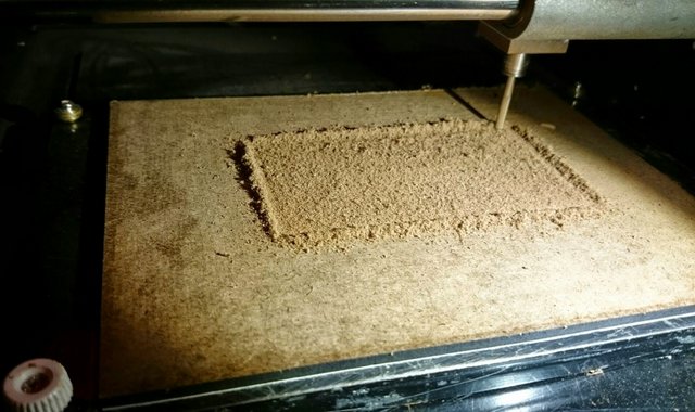
Milling the bed! 45 minutes each pass...
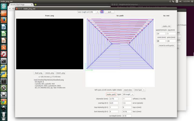
The fab module with the PNG. and the settings!
Electronics Design Video Review at 1:19:05