measure something: add a sensor to a microcontroller board that you've designed and read it
In this module we faced whit Input Devices, the lesson of Neil was very interesting, it is the first time I get close to this level of electronics and I really want to try this experience!
Here is a very clear definition I found on Wikipedia about Input Devices, an input device is a peripheral used to Shops provide data and control signals to an information processing system: such as a computer or other information appliance.
For my final project I will not need systems with input devices, so I choose to experiment with step response.
I will try to make the touchpad, as suggested in the example sheet lesson.
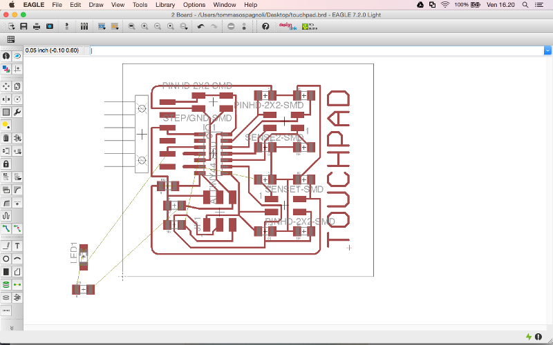
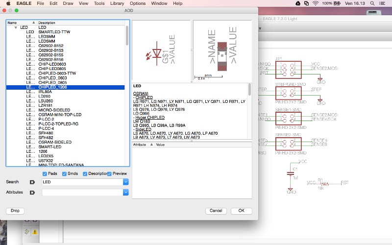
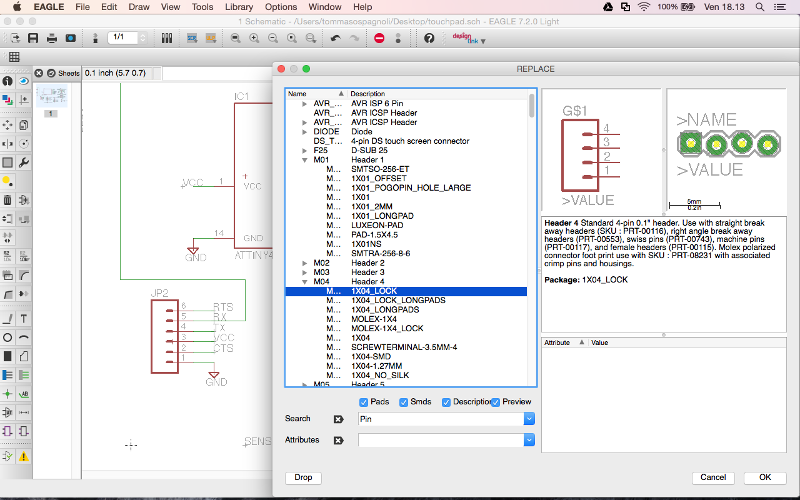
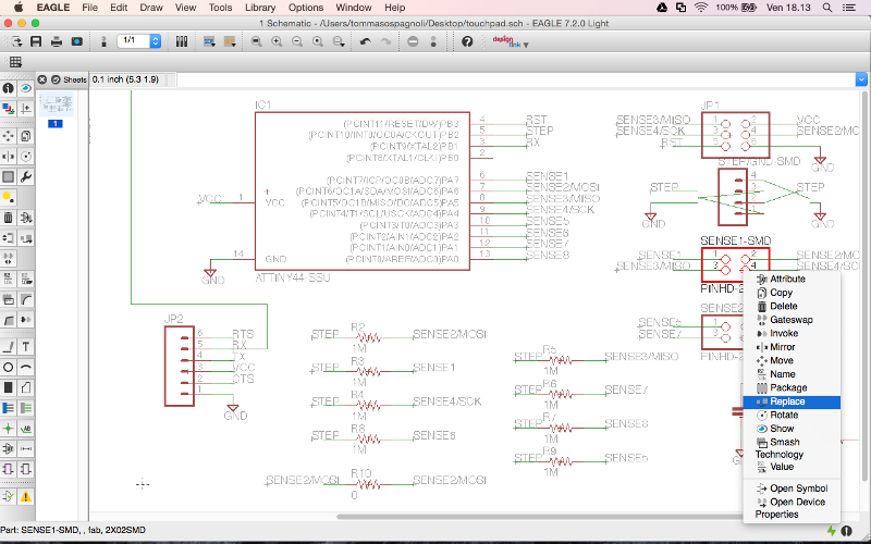
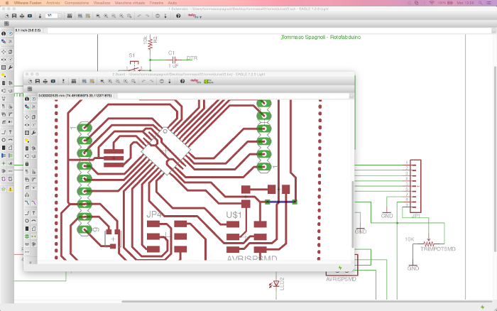
I first downloaded the file Egle and I opened the existing project, then I added 1 LED and a resistance, so I changed the position in the board design.
Egle is composed of two different views, the main components are used to charge and close the circuit. In the second view, you can place the design of the card, but you must be very careful to create the space needed to weld the elements without superimposing lines and calculating the space for the tip of the milling machine.
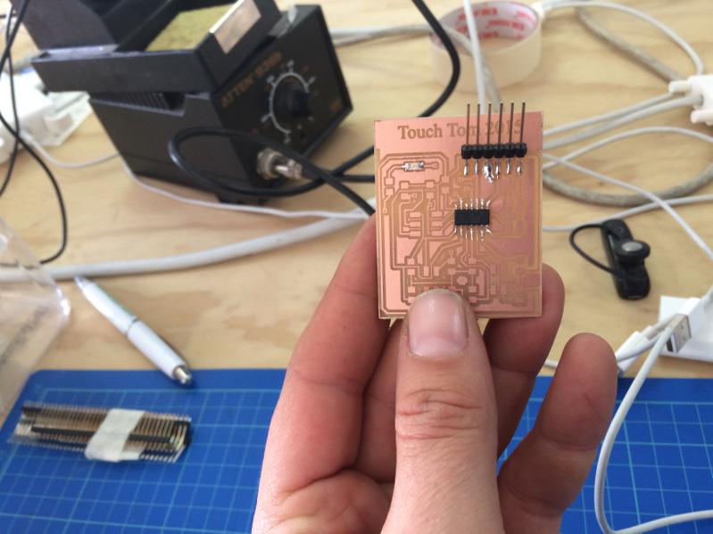
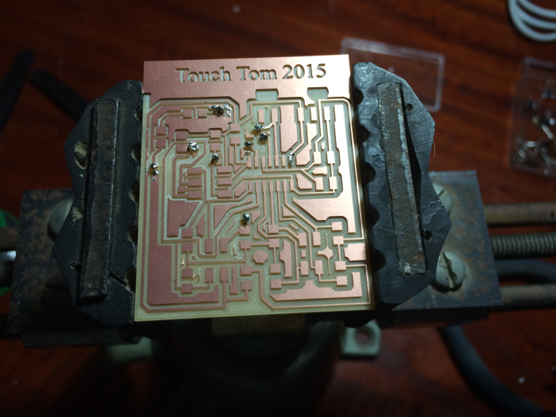
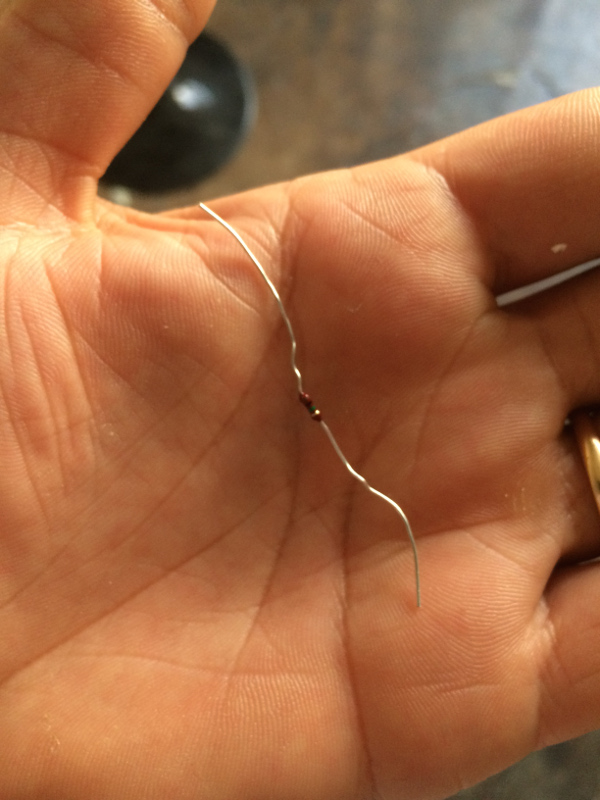
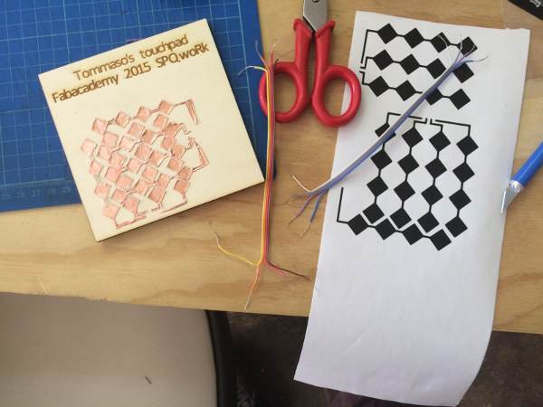
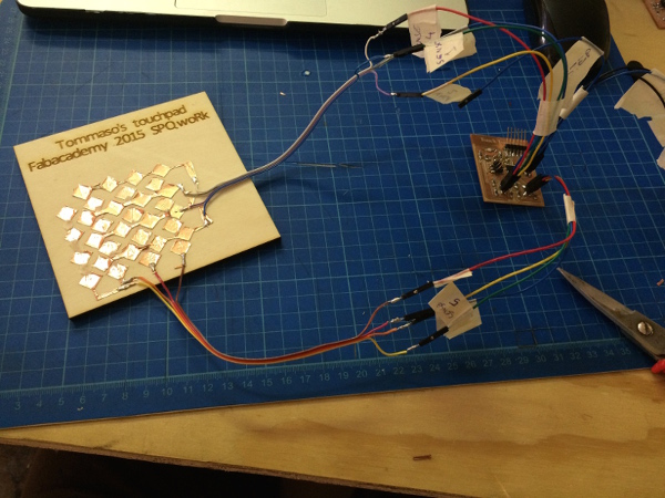
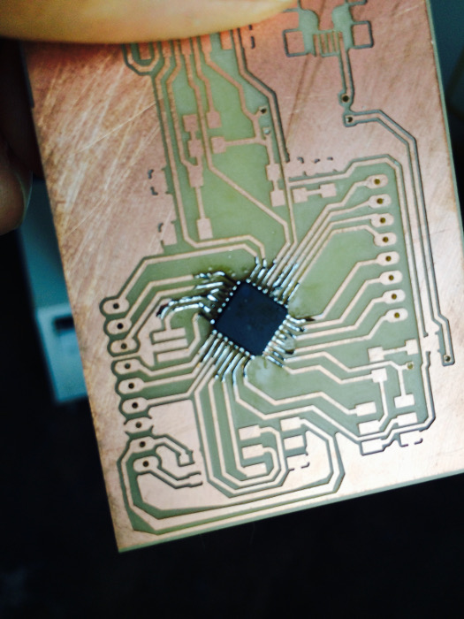
I made a capacitive touchpad with an ATTiny44 micro controller which measures input voltage on a number of copper pads using step response.
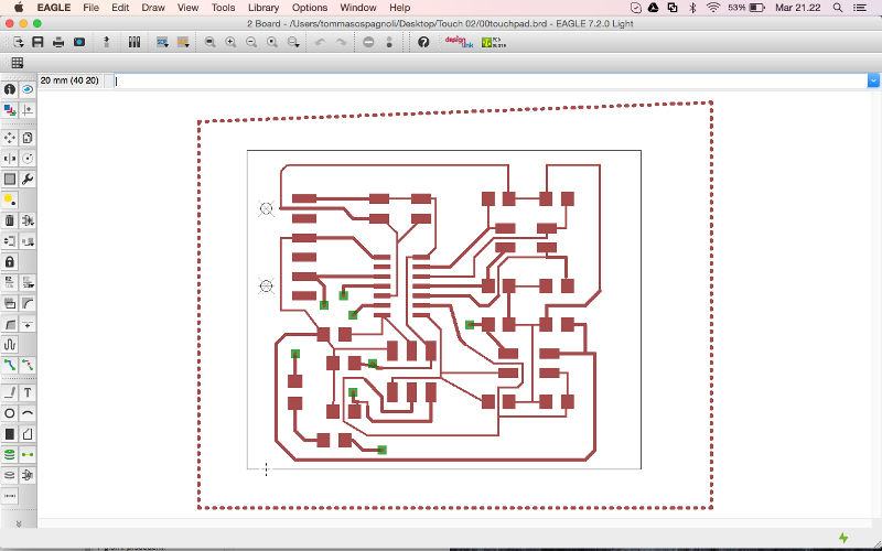
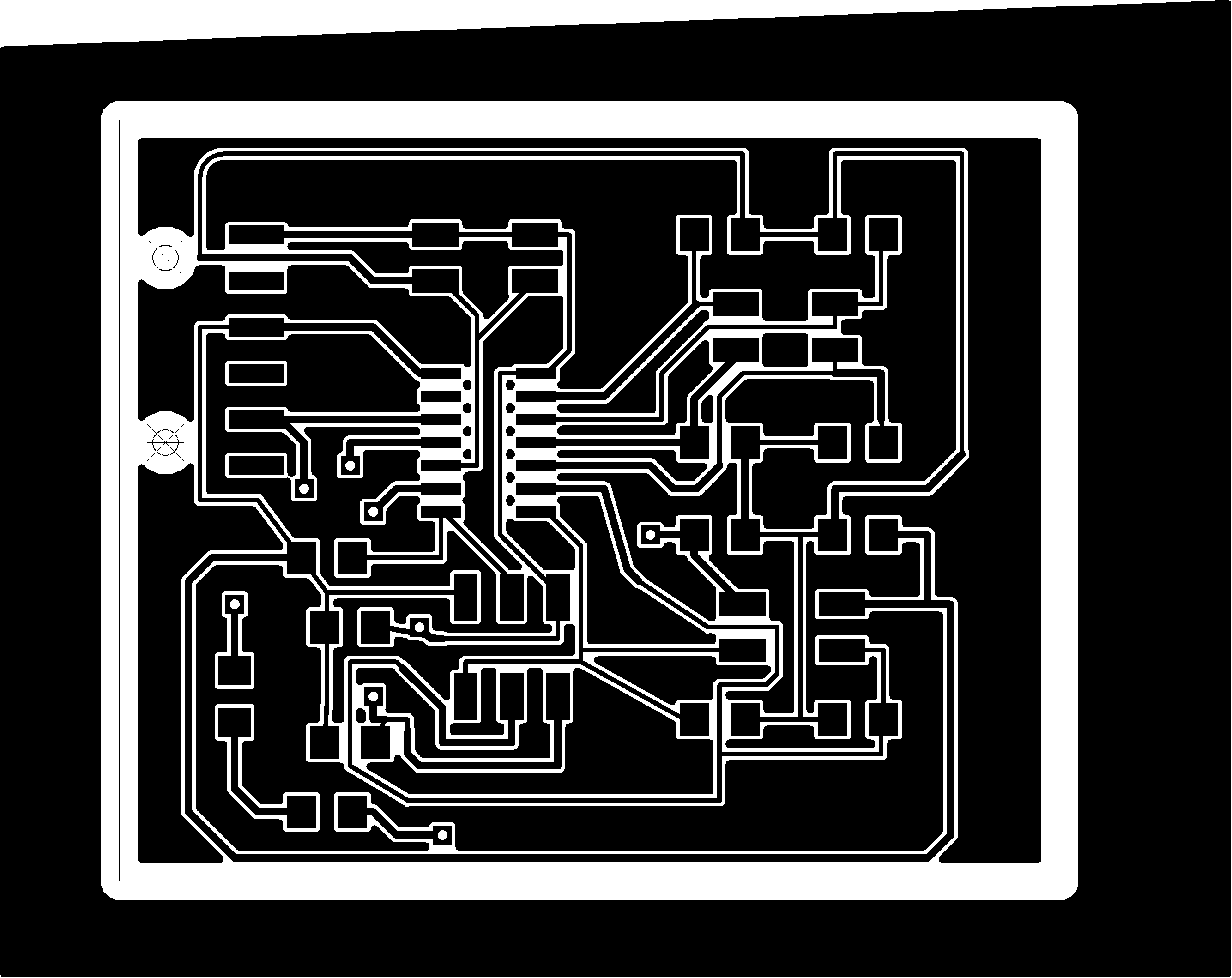
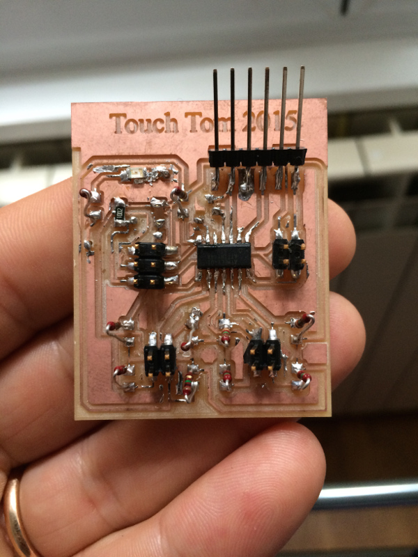
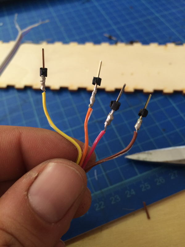
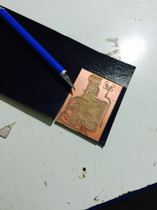
After working with Eagle, I switched to using Vectric and Corel Drow. I spent a lot of time cleaning the tracks, unfortunately exporting files from Eagle lost several details. I managed to drill with good results and now I'm welding the elements.
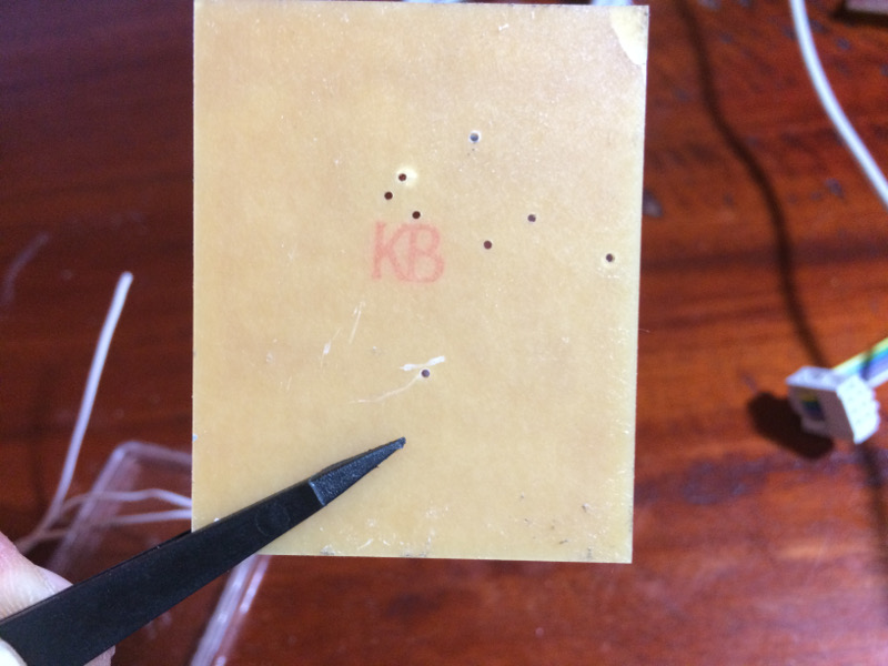
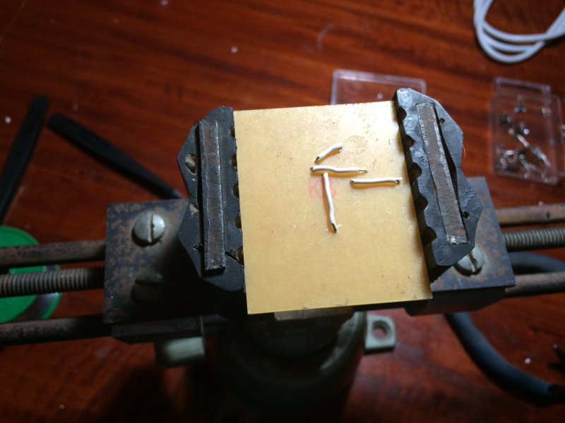
This time I decided to make holes behind the board for passing the bridges that would otherwise be cumbersome on the front of the card , is a soluziine I've Seen it very useful to settle more comfortably.
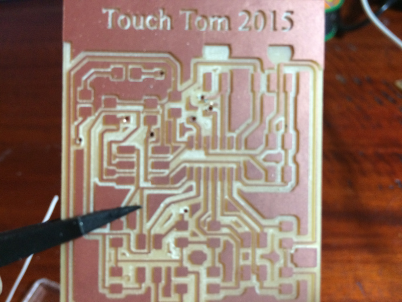
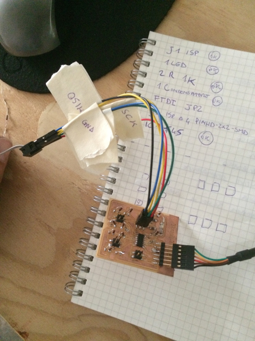
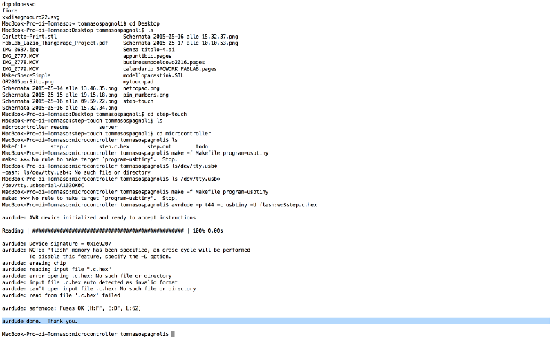
This was for me the most complicated form, for 3 times I milled and welded the tab every time after welding smooke I made the test and yet the board fails to make the botloader. During the first attempt I was short of resistors 1kohm, so I made use of another type of resistance, always of the same value. Fortunately after olt attempts I managed to program the card!
To create the crusore I designed and laser cut plywood 4 mm thick, measuring 200mm x 200mm, after I tried to cut it with the vinylcut a copper film, but unfortunately the blade was not sharp enough, so I had to do by my hend!

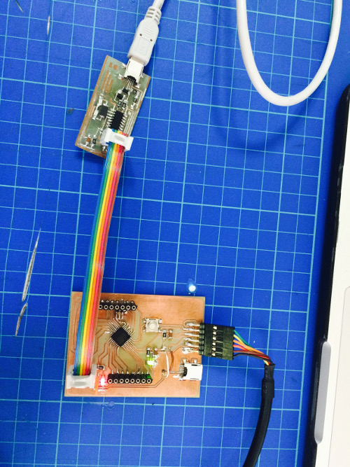
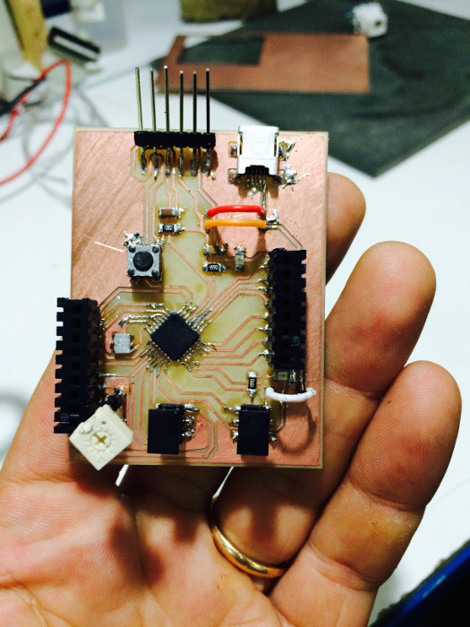
I created a card , a clone of the Arduino I called Rotomolduina . Rotomolduina has a ATtiny 328 , 6-pin and 8 -pin digital analog . It ' was really hard , I made the card for 6 times before being able to program it , the slopes were always very close to each other and often false contacts near the microcontroller were impossible to recover!
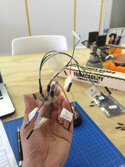
The advice I can give is to make sure the tracks " comfortable " to be welded at the risk of throwing away time , components and copper rods!
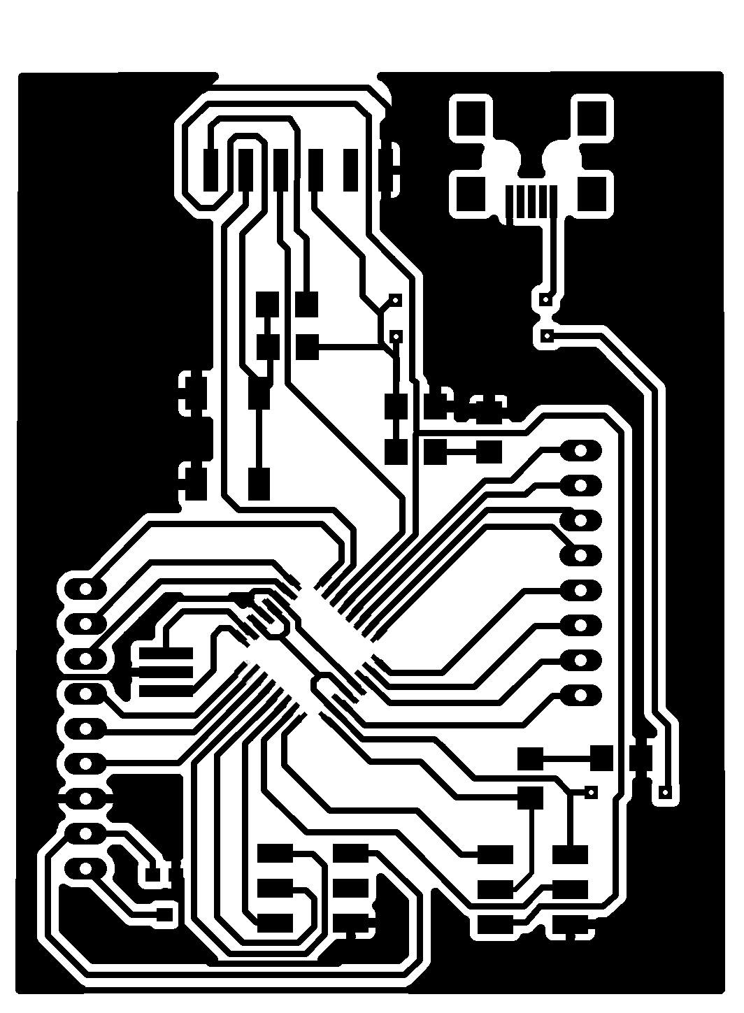
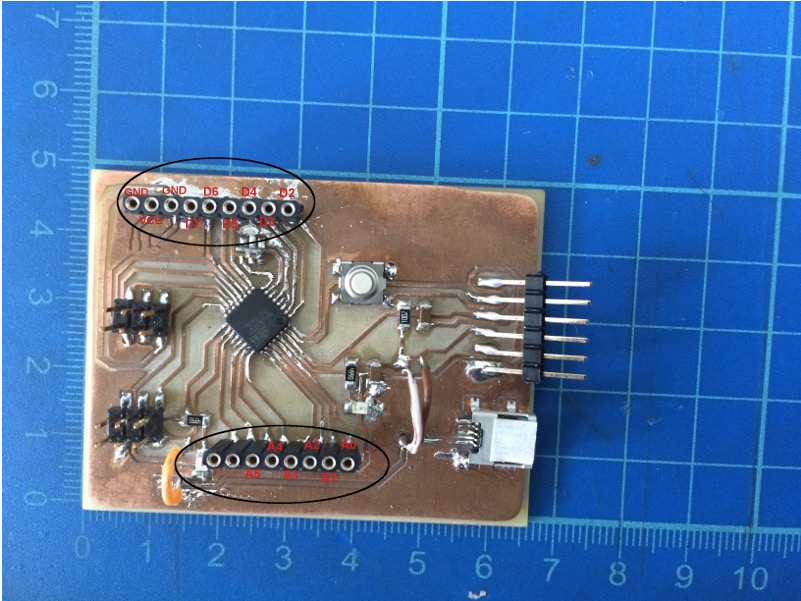
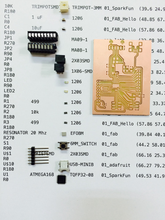
That's how it is composed Rotmolduina
10K TRIMPOTSMD TRIMPOT-3MM
C1 1uF
C4 10uF
JP1
JP2
JP4
JP8
LED
LED2
R1 99
R2 10k
R3 499
RESONATOR 20 Mhz
S1 6MM_SWITCH
U$1 AVRISPSMD 2X03SMD
U$10 USB-MINIB
U1 ATMEGA168 TQFP32-08
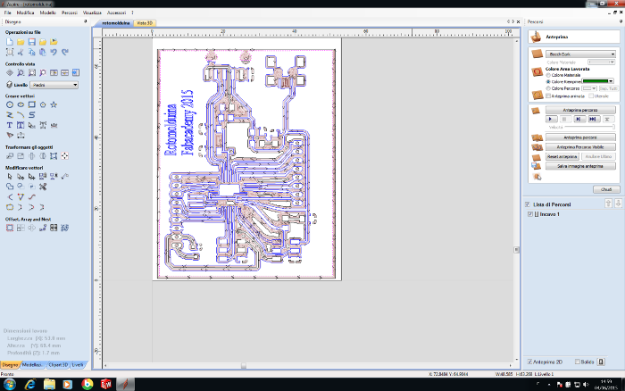
After working with Eagle and the rooting of the board, I exported the file as PNG to another resolution and imported the same file on Aspire.
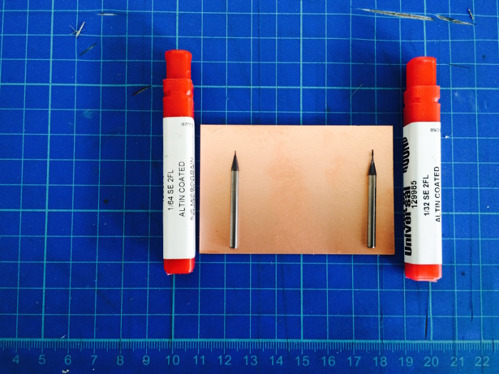
With Aspire I made modufiche necessary to ensure the passage of the cutter, with ores software thanks to the "Calculate" you can not figure out where to go and where to pass the cutter during machining, is set imprtante measures of the board and the measures of the tips . For this work I using the shell tips for feesatura 1/64 and 1/32 for cutting and holes. Aspire to the file is exported in text files, one file for each function, eg. one for cutting, one for milling etc etc ..
With text files, the cutter is used Mach 3, first of all placing the copper bar, then it is brought to 0 the Z-axis, consequently the axes X and Y, always making sure the right towards cutting. Mach 3 allows you to upload files in txt and thanks to a slider on the right side of the screen you can see the simulation work.
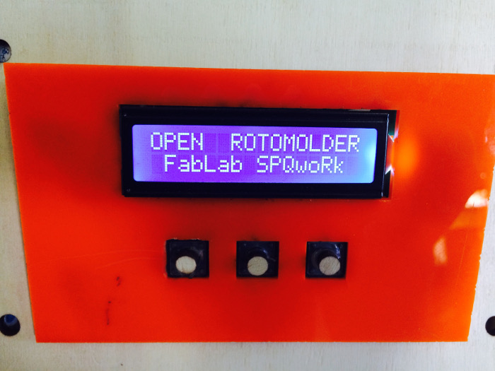
With the same system I made the keyboard to control the LCD monitor.
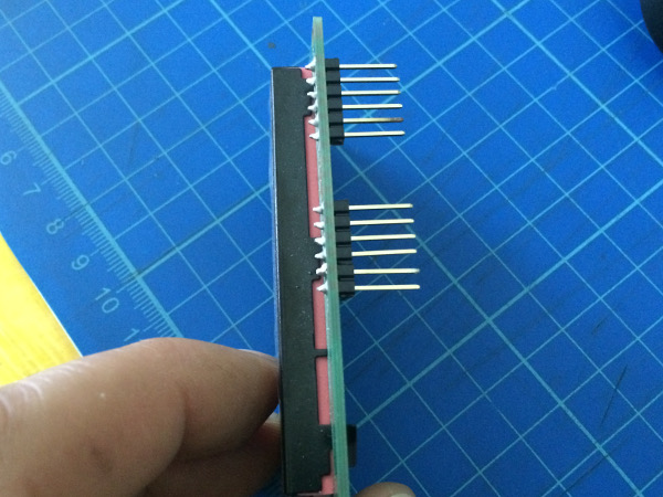
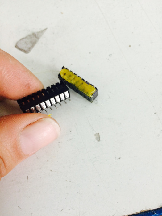
The first time I soldered pins on the card I had to use most of the time , so I used hot glue to prevent the short circuit , another solution to protect the board is to use a static bottom to absorb the waves electromagnetic we send to the board, many jobs have been lost because of similar reasons , and after days and days of work I advise everyone to predere precautions.
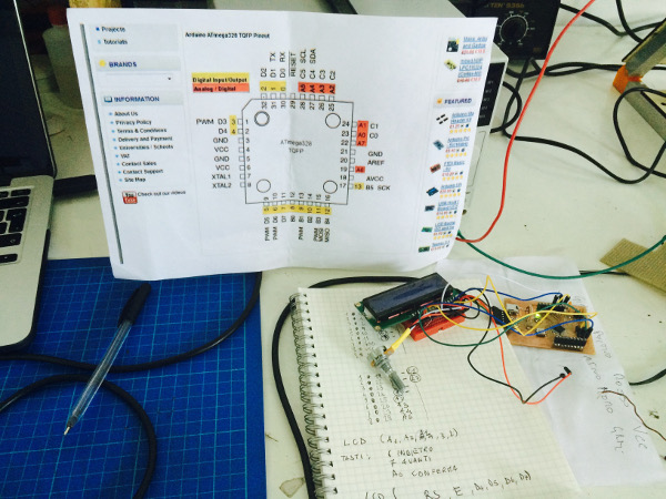
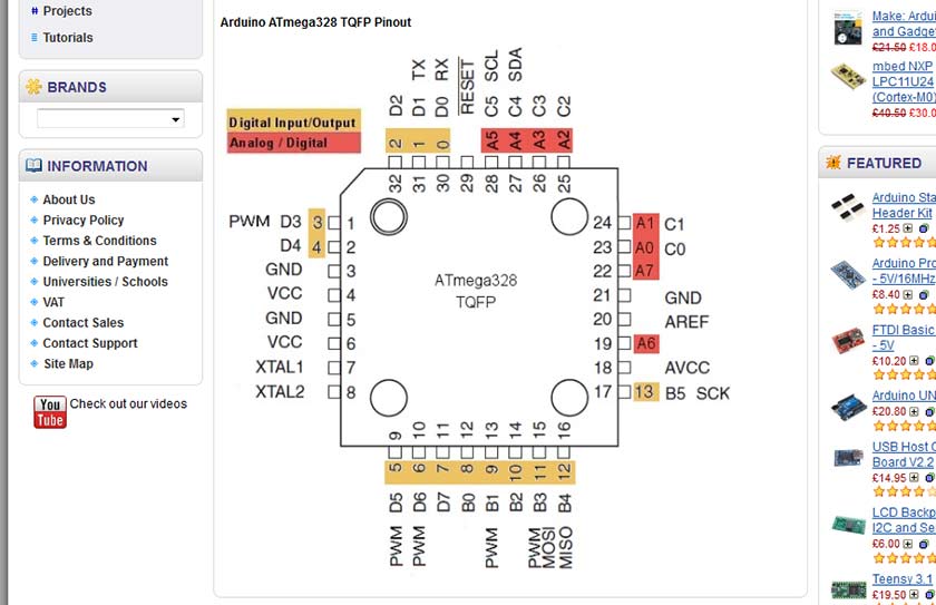
The first step was to run the ldc monitor , then I wrote a very simple program for Arduino , here follows the identification of pin :
/*
LCD 16 caratteri x 2 righe
pin del circuito LCD:
* LCD RS pin to digital pin 7
* LCD Enable pin to digital pin 6
* LCD D4 pin al digital pin 5 +
* LCD D5 pin al digital pin 4 +
* LCD D6 pin al digital pin 3 +
* LCD D7 pin al digital pin 2 +
* LCD R/W pin al ground
* LCD VSS pin al ground
* LCD VCC pin al 5V
* 10K pot
* ends to +5V and ground
* wiper to LCD VO pin (pin 3)
*************************
This is the program compoleto arduino , with engines and lcd monitor , at the bottom of this page you can scricare file Arduino to replicate the program.
pin dei tasti:
*Tasto indietro al digital pin 6
*Tasto avanti al digital pin 7
*Tasto conferma al digital pin 8
***********************************************
pin controllo motore posto in OUT A:
*pin controllo 1 al digital pin 10
*pin controllo 2 al digital pin 13
*pin enableA per la velocità al digital pin PWM 9
*/
// libreria dello schermo LCD
#include
//definizione dei pin dei tasti e del motore
#define pinMotoreA 10
#define pinMotoreB 13
#define pinMotoreE 5
#define pinIndietro 6
#define pinAvanti 7
#define pinConferma A0
//creo un carattere custom un blochetto tutto nero
byte blocco[8] =
{
B11111,
B11111,
B11111,
B11111,
B11111,
B11111,
B11111,
B11111
};
//definizione schermata iniziale
static char Intro0[15] = "OPEN";
static char Intro1[15] = "ROTOMOLDER";
static char Intro2[15] = "FabLab SPQwoRk";
//definizione schermata menu principale
static char Posizione1[15] = ">> Direction";
static char Posizione2[15] = ">> Velocity";
static char Posizione3[15] = ">> Program";
// inizializzazione dei pin dello schermo LCD
LiquidCrystal lcd(7, 6, A5, A4, A3, A2);
//variabili
int vel =0;
void setup() {
// dichiara il numero di caratteri e di righe del nostro schermo
lcd.begin(16, 2);
//attivo il nuovo carattere
lcd.createChar(0, blocco);
//definizione stato dei pin
pinMode(pinMotoreA, OUTPUT);
pinMode(pinMotoreB, OUTPUT);
pinMode(pinMotoreE, OUTPUT);
pinMode(pinIndietro, INPUT);
pinMode(pinAvanti, INPUT);
pinMode(pinConferma, INPUT);
//schermata di reset
for(int n = 0; n < 16; n++)
{
lcd.setCursor(n,0);
lcd.write(byte(0));
lcd.setCursor(n,1);
lcd.write(byte(0));
delay(50);
}
// schermata Principale
Intro();
Serial.begin(9600);
}
void loop() {
lcd.setCursor(0, 1);
int avanti=digitalRead(pinAvanti);
int indietro=digitalRead(pinIndietro);
int conferma=digitalRead(pinConferma);
if (avanti==HIGH || indietro ==HIGH || conferma == HIGH){
Menu();}
}
void Intro(){
lcd.clear();
lcd.setCursor(0,1);
lcd.write(" ");
for(int n = 0; n < 4; n++)
{
lcd.setCursor(n,0);
lcd.write(Intro0[n]);
delay(50);
}
lcd.setCursor(4,0);
lcd.write(" ");
for(int n = 0; n < 16; n++)
{
lcd.setCursor(n+6,0);
lcd.write(Intro1[n]);
delay(50);
}
for(int n = 0; n < 16; n++)
{
lcd.setCursor(n+1,1);
lcd.write(Intro2[n]);
delay(50);
}
lcd.setCursor(15,1);
lcd.write(" ");
}
void Menu(){
boolean PosizioneSelezionata = false;
int avanti=digitalRead(pinAvanti);
int indietro=digitalRead(pinIndietro);
int conferma=digitalRead(pinConferma);
lcd.setCursor(0,0);
lcd.write("SELECT VELOCITY ");
if(avanti==HIGH && vel-3){
vel++;}
else if(indietro==HIGH && vel>0){vel--;}
Serial.println("vel ="+ vel);
delay(500);
switch(vel){
case 0:{
lcd.setCursor(0,1);
lcd.write(" MOTOR STOP! ");
if (conferma==HIGH){
Serial.println("Fermo");
digitalWrite(pinMotoreA,LOW);
digitalWrite(pinMotoreB,LOW);}
break;}
case 1:{
lcd.setCursor(0,1);
lcd.write(" MEDIUM SPEED ");
if (conferma==HIGH){
Serial.println("Lento");
digitalWrite(pinMotoreA,HIGH);
digitalWrite(pinMotoreB,LOW);
analogWrite(pinMotoreE, 125);}
break;}
case 2:{
lcd.setCursor(0,1);
lcd.write(" HIGH SPEED ");
if (conferma==HIGH){
Serial.println("Veloce");
digitalWrite(pinMotoreA,HIGH);
digitalWrite(pinMotoreB,LOW);
analogWrite(pinMotoreE, 255);}
break;}
}
}
void drawMenu (int posizione)
{ switch ( posizione ) {
case 0:
{
lcd.clear();
for(int n=0;n - 16; n++)
{lcd.setCursor (n,0);
lcd.write(Posizione1[n]);
lcd.setCursor(n,1);
lcd.write(Posizione2[n]);
}
lcd.setCursor(12,0);
lcd.write(" ");
lcd.setCursor(11,1);
lcd.write(" ");
break;}
case 1: {
lcd.clear();
for(int n=0;n-16; n++)
{lcd.setCursor(n,0);
lcd.write(Posizione2[n]);
lcd.setCursor(n,1);
lcd.write(Posizione3[n]);
}
lcd.setCursor(11,0);
lcd.write(" ");
lcd.setCursor(10,1);
lcd.write(" ");
break; }
}
}
void SelezionaVelocita(){}
void SelezionaDirezione(){}
void SelezionaProgramma(){}
void MotoreDestra(){
digitalWrite(pinMotoreA,LOW);
digitalWrite(pinMotoreB,HIGH);}
void MotoreSinistra(){
digitalWrite(pinMotoreA,HIGH);
digitalWrite(pinMotoreB,LOW);}
void Velocita(int valVel){
analogWrite(pinMotoreE,valVel);}