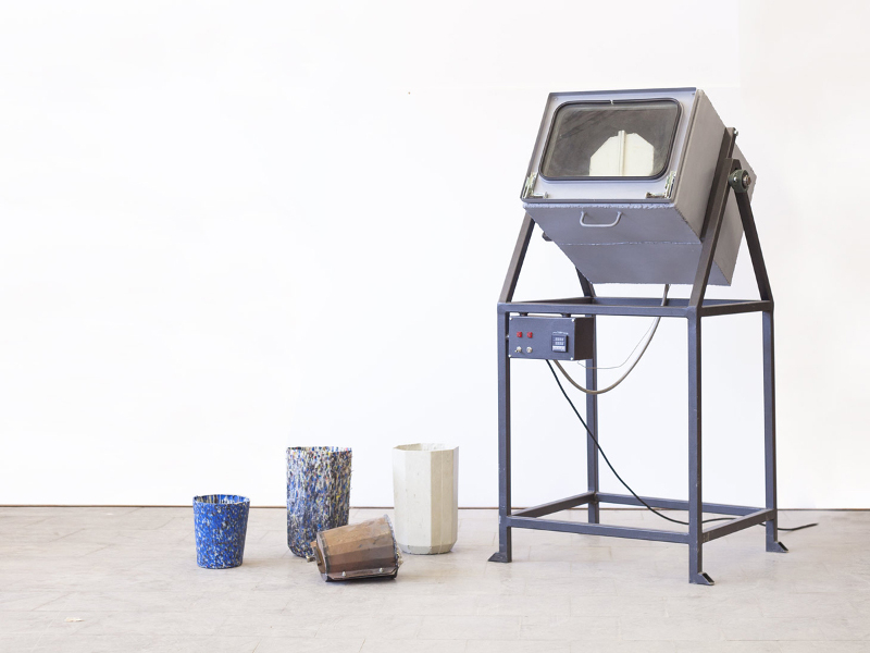
With the popularity of DIY 3D printing, you now have the ability to create one 3D object in a relatively short amount of time, but printing multiple objects is still a time consuming process. I was looking for a way to increase the speed of reproducing 3D printed parts, so i stumbled upon rotational molding and spin casting. With this technique you can reproduce many identical parts from a successful 3D print. Rotational molding machines are made in a wide range of sizes (example). They normally consist of moulds, an oven, a cooling chamber, and mold spindles. The spindles are mounted on a rotating axis, which provides a uniform coating of the plastic inside each mold.
A small DIY Rotational Casting Machine is a solution to bridge the gap between rapid prototyping and the cost of producing thousands of hollow cast parts.
A mold filled with resin is placed into the " Roto-molding Machine " where it is slowly rotated (usually around two perpendicular axes) causing the liquid resin to uniformly disperse and stick to the walls of the mold where it slowly cures over time into the shape of the part. In order to maintain an even thickness throughout the part, the mold continues to rotate at all times during casting phase and curing phase.
One of the major advantages of " Roto-molding Machine " a hollow part is the savings in materials and weight. If an object does not require to be solid, why cast it solid and waste materials?
Rotational Molding involves a heated hollow mold which is filled with a charge or shot weight of material. It is then slowly rotated (usually around two perpendicular axes) causing the softened material to disperse and stick to the walls of the mold. In order to maintain even thickness throughout the part, the mold continues to rotate at all times during the heating phase and to avoid sagging or deformation also during the cooling phase. The process was applied to plastics in the 1940s but in the early years was little used because it was a slow process restricted to a small number of plastics. Over the past two decades, improvements in process control and developments with plastic powders have resulted in a significant increase in usage. Rotocasting (also known as rotacasting), by comparison, uses self-curing resins in an unheated mould, but shares slow rotational speeds in common with rotational molding. Spin casting should not be confused with either, utilizing self-curing resins or white metal in a high speed centrifugal casting machine.
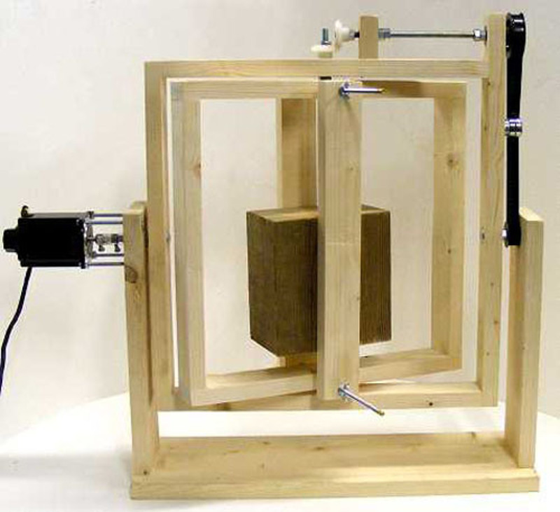
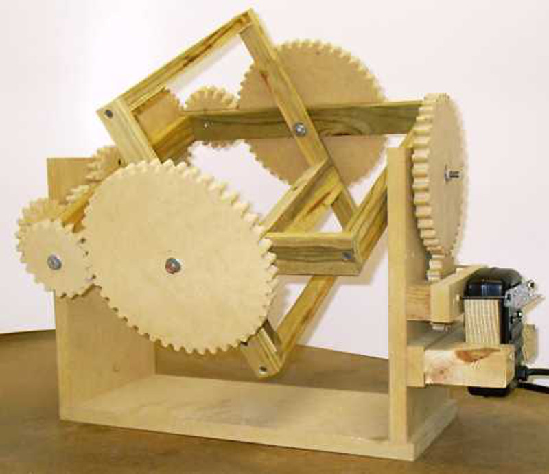
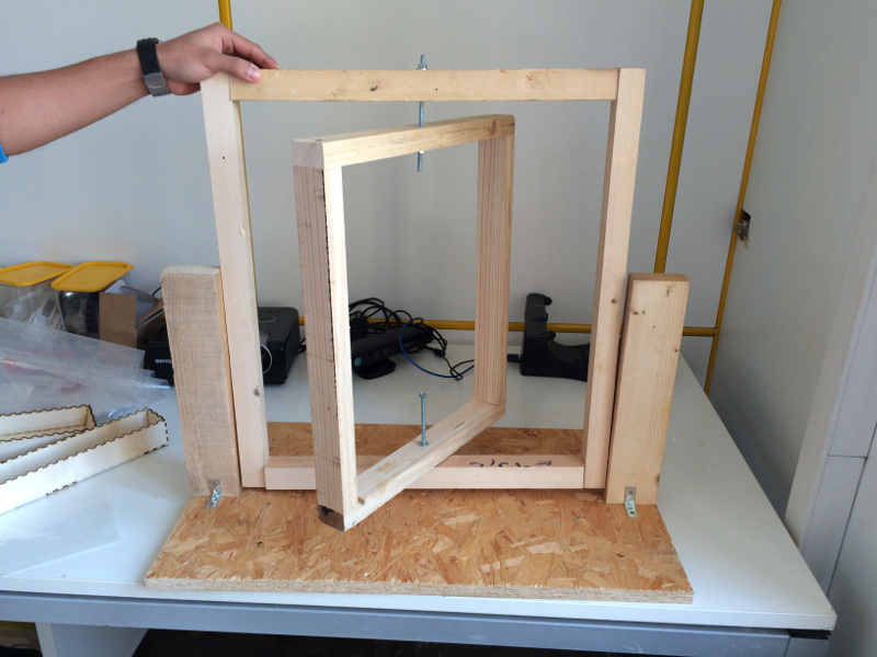
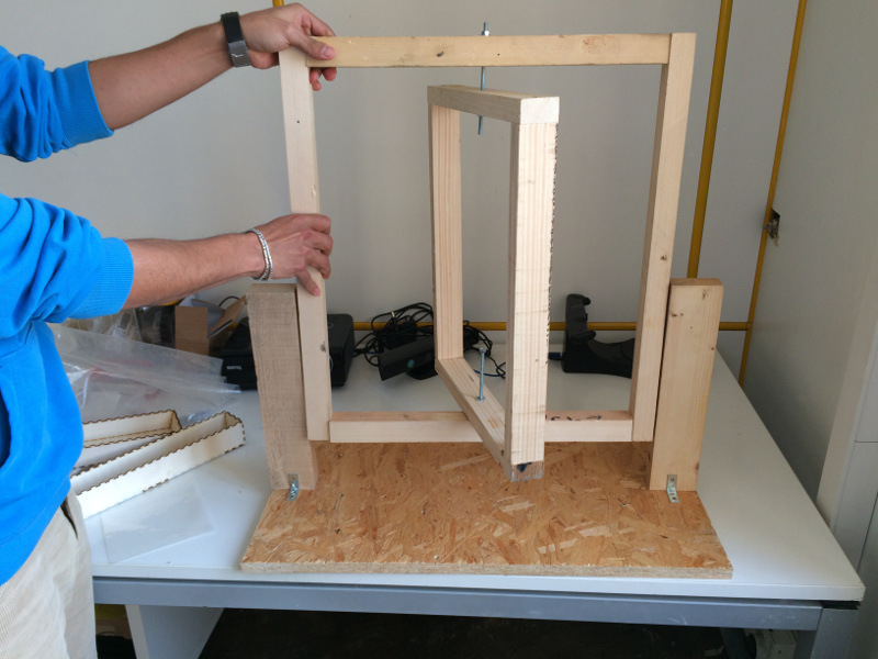
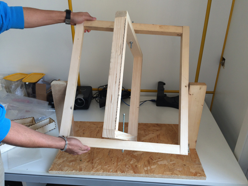
Basic should not have trouble creating a Rotomoulding Machine in the traditional way, using wood cut with the saw and joined with screws. The real challenge is to bring back the traditional creation of a project of digital fabrication, and open design, easily reproducible and less possible elements. I got to see so many models of rotomolding online, some motorized and other manuals, some very large and several smaller ones. A rotomoldign is composed of a base static and two dynamic frames, which rotate horizontally and vertically to distribute the resin in every part of the mold. The machine I have in mind must be able to stand on a desk, it must have the clutter that has a classic 3d printer, imagine this machine with one motor and a manual control to change the speed of rotation of the two dynamic elements.

Bill of materials
Tools
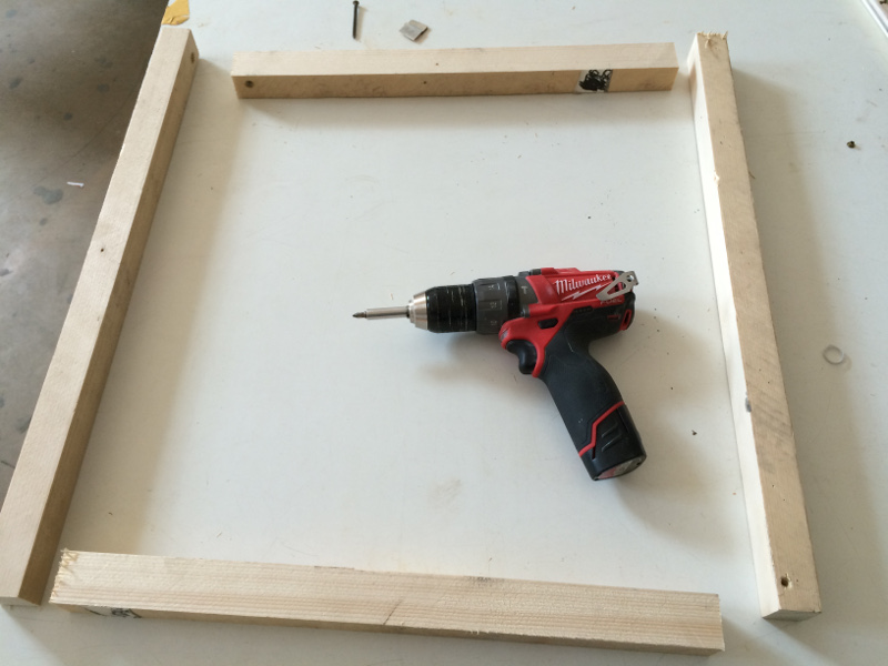
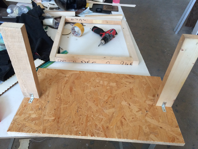
I start whit this first experiment serves to make me understand the sizes and proportions of the car I want to accomplish. The process is apparently very spartan, but I assure you that I served a lot to plan then work with a graphics program.
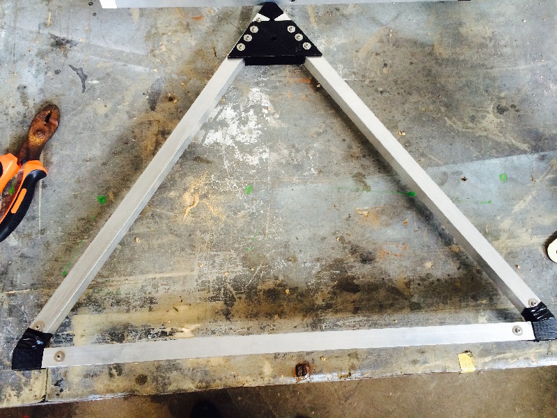
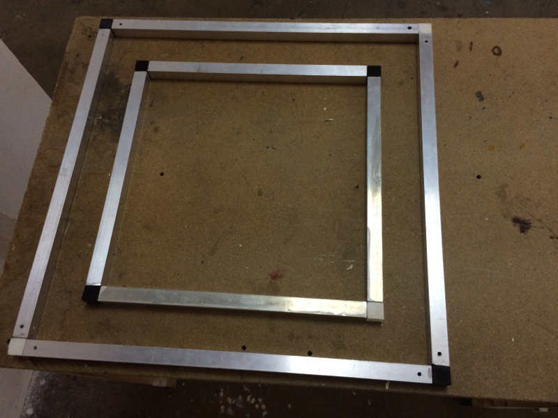
I cut the wood base OSB with thickness 20mm, width 400mm x 700mm length, then I created two frames, one inside the other.
The frame has the larger base of 500mm and height of 600mm, the smaller frame has a base of 500mm and height of 400mm. The two vertical rods that hold the frames 350mm high and 70mm wide.
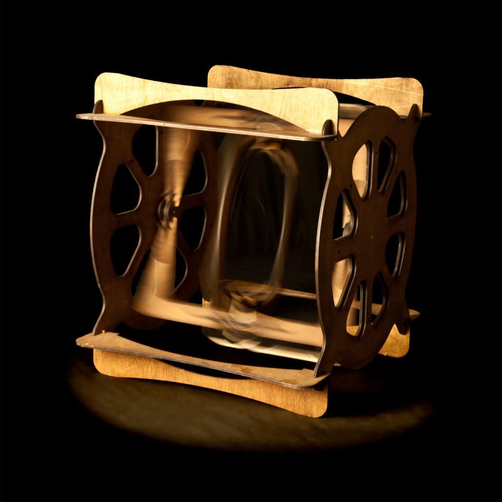
The machine is the scaled-down replay of molding machines in centrifugal casting and rotational molding. Compared to the centrifugal casting is distinguished by the use of liquid resins with respect to molten materials, rotational molding retrieves the handling mode of the mold.
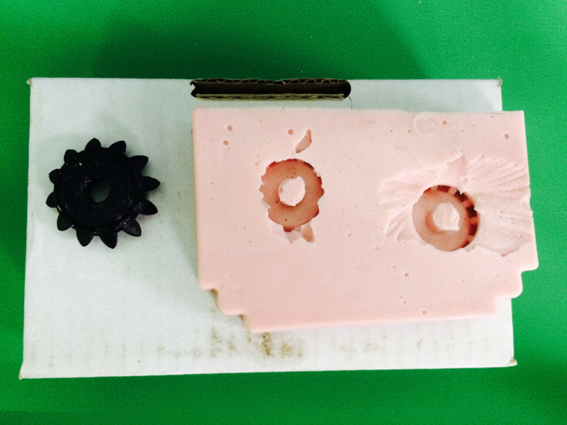
Through the use of special liquid silicones it is possible to obtain the mold of the object to replicate: the elastic properties of silicon allow to realize a mold partially openable to allow the extraction of the initial model, first, the casting then solidified. Said melt is obtained by partial filling of the mold with resins bi-component set in rotation centrifugal bi-asiale inside the mold. This allows to obtain empty objects, light and strong, and achieve a considerable saving in terms of material used.
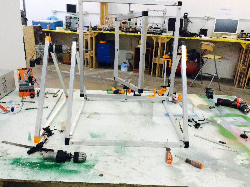
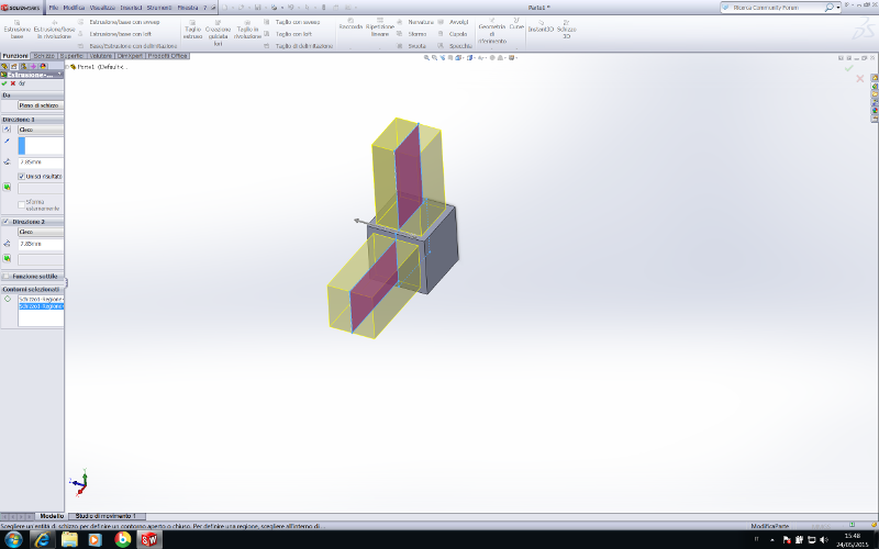
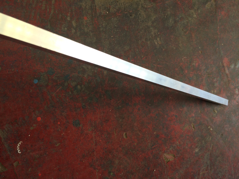
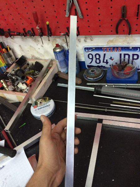
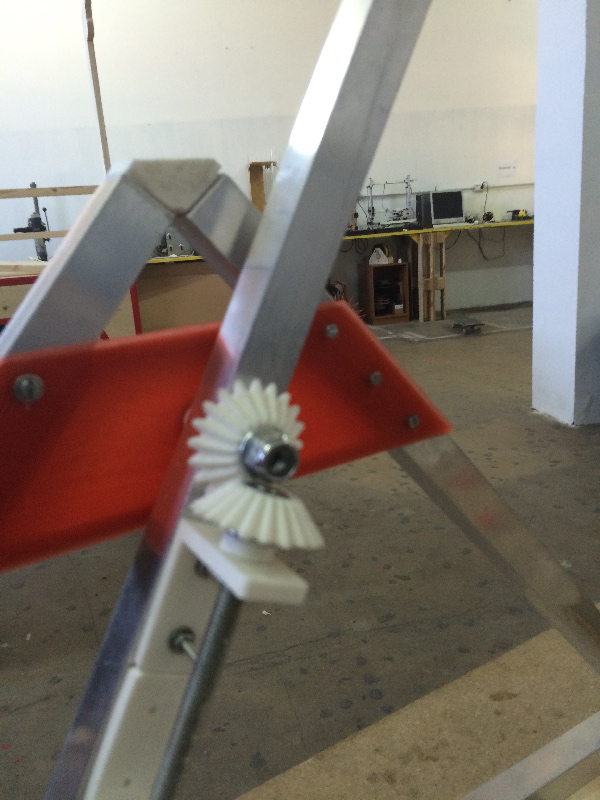
To make the structure more stable and robust , I decided to use the aluminum bars instead of wood , molded parts in 3D that I will go to replicate resin thanks to silicone molds . I will use also the plexyglas for housing the counterweight and to maintain stable the object to be machined.
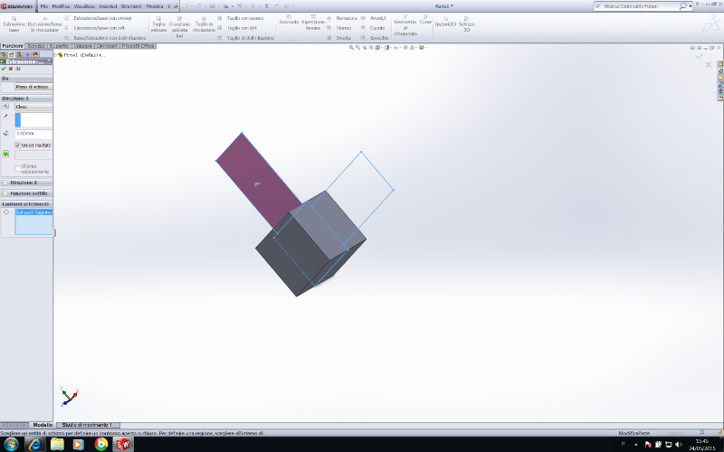
I used Solidwork for modelling in 3d.
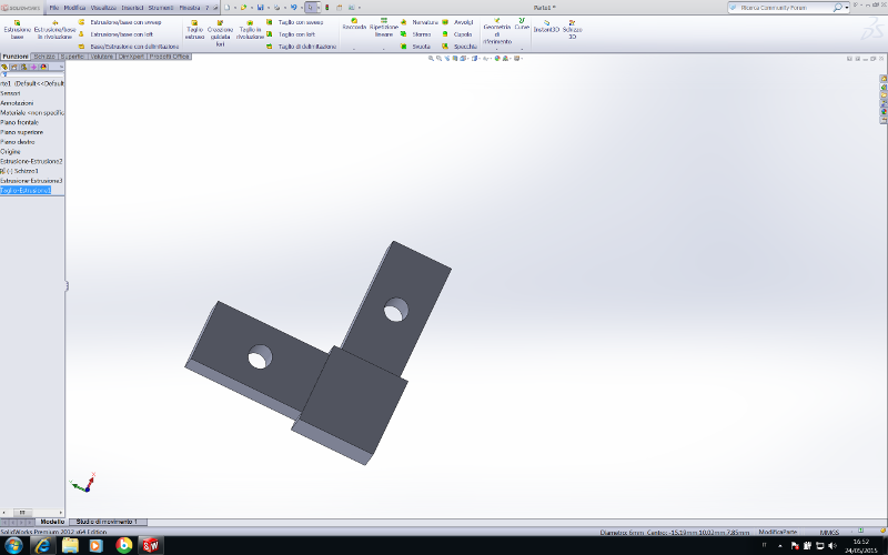
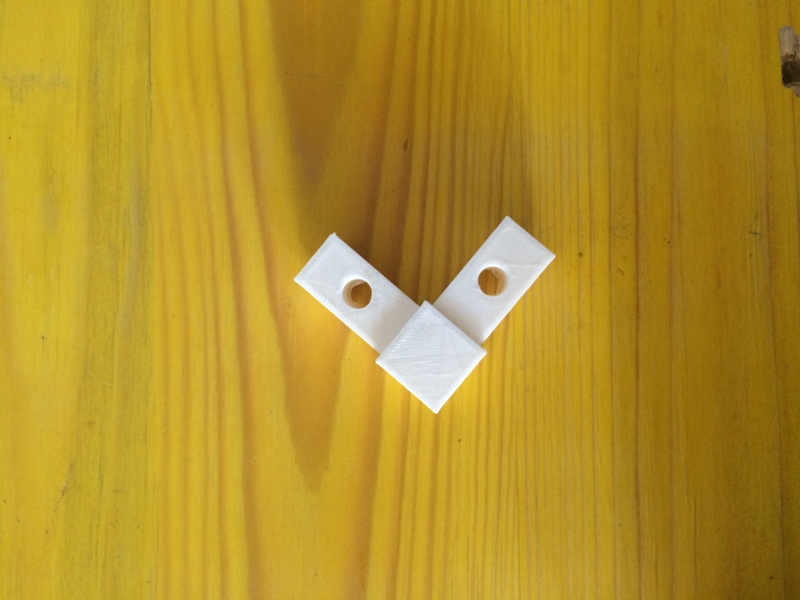
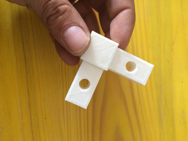
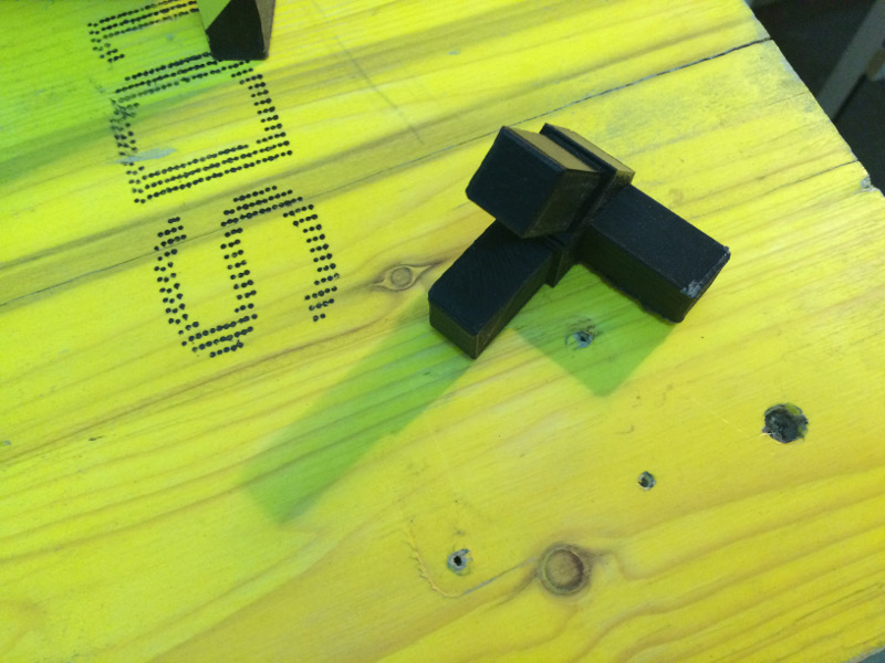
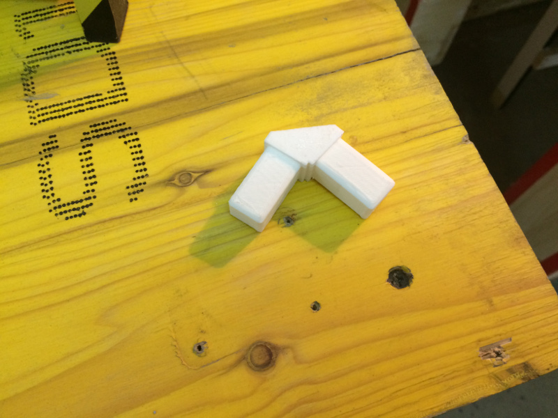
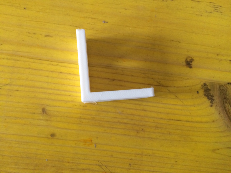
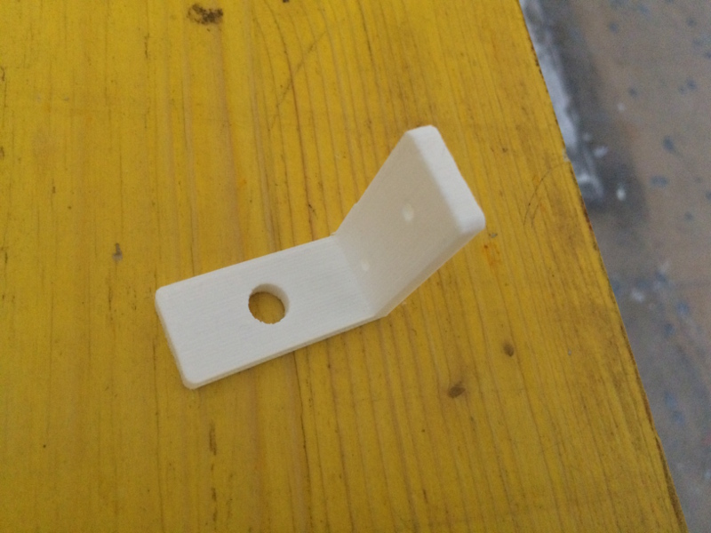
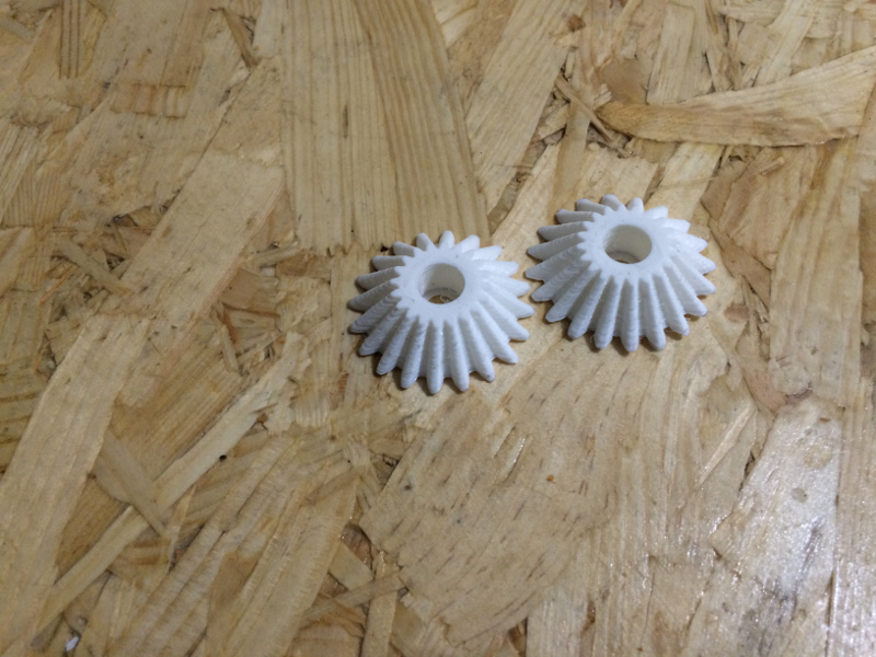
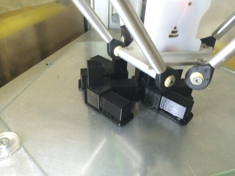
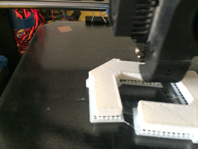
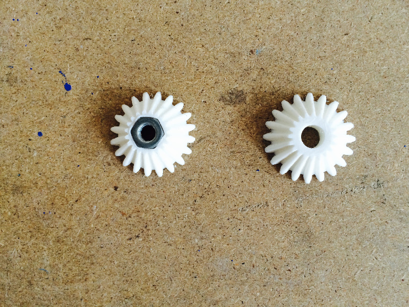
The molded parts in 3d are 11
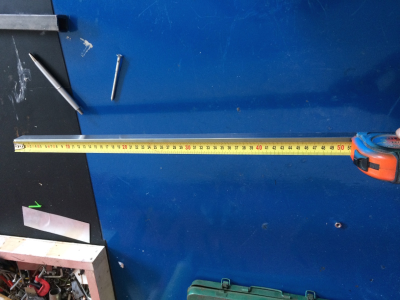
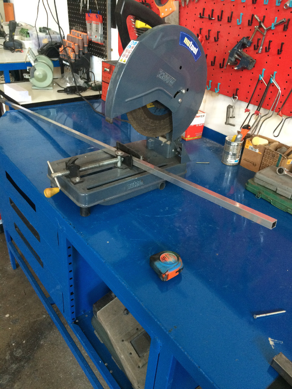
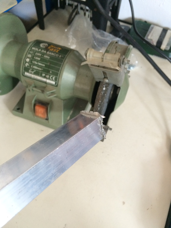
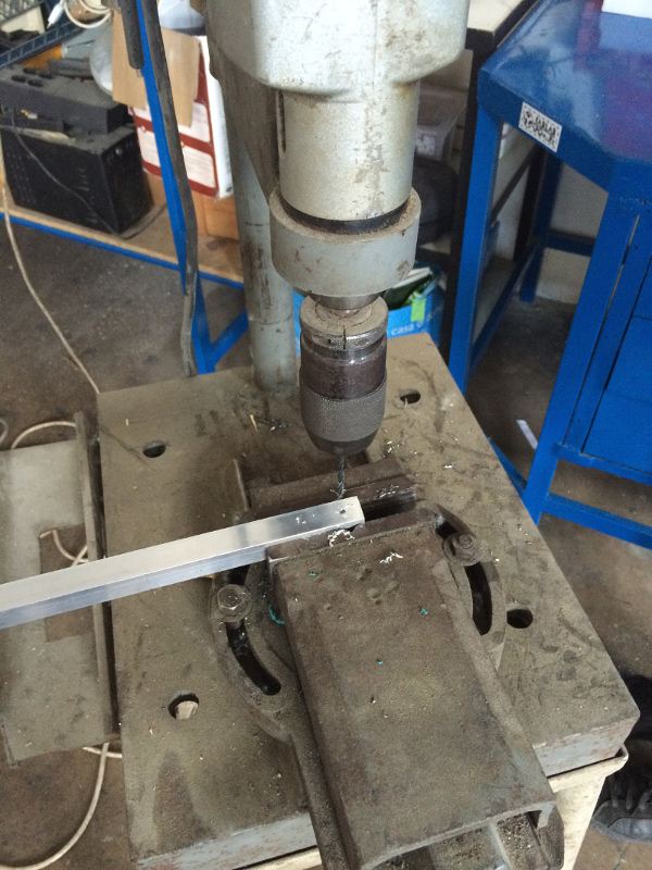
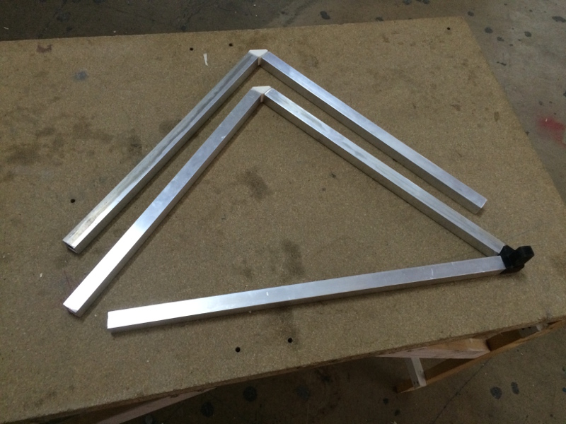
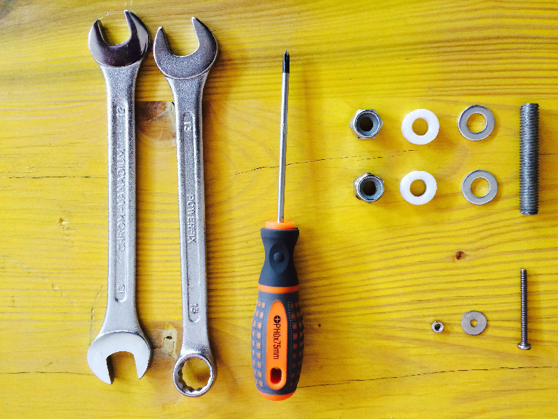
For the realization of the frame , I bought 2 aluminum bars from 650 cm , at a cost of 18 € each bar . In the laboratory I cut the bars before the hacksaw , then I finished with a grinding wheel electric .
To compose the frame are necessary
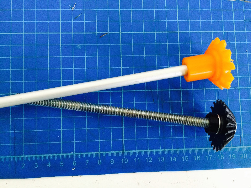
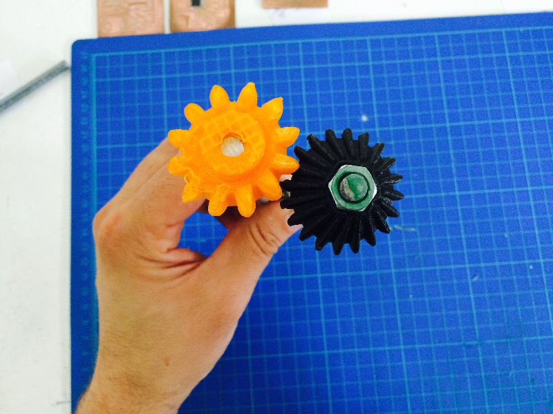
The mechanical structure of this machine is very complex , I worked a lot on the gears , during the first phase of prototyping I commited many mistakes . The first error was to use of the ferrules not transmitted between them , the inlets were not deep enough so the ring nut without slipping hook the opposite ring . So I modeled with Solid Works new pieces and I made four types of nuts . The first flat , so as to have the least possible obstruction , other 2 with an extrusion of 10 mm , one forward and the other backward , to occupy less space between the structures . The fourth ring nut instead is one that technically more complex , because it presents an extruded cut for housing a bearing , this ring is positioned below the small inner frame and anchored to the same , it receives the last transmission and allows the frame to rotate by exploiting the movement of previous.
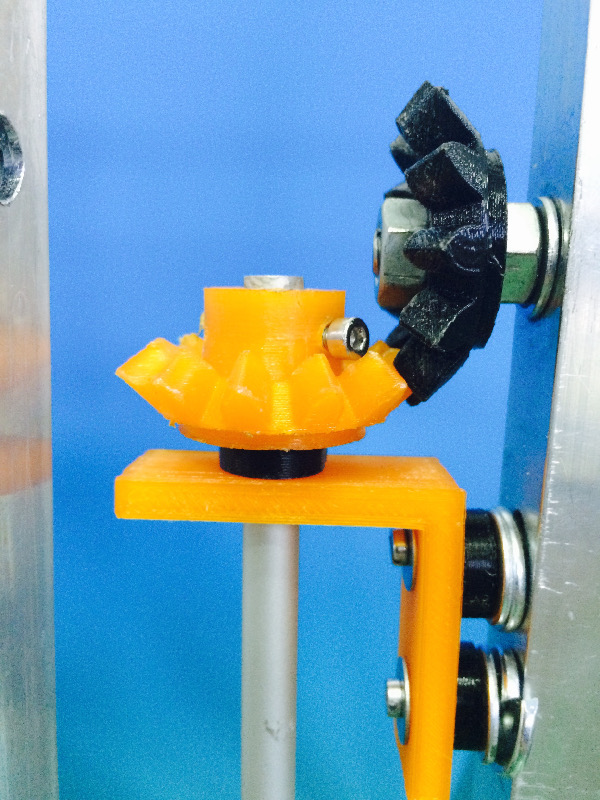
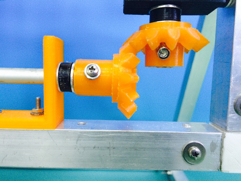
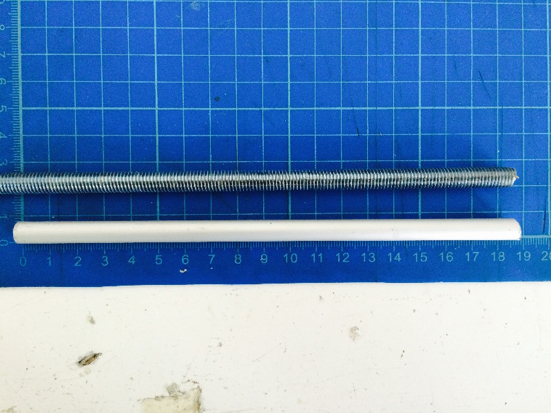
Another mistake I made is that of using threaded rods from 8mm in diameter and 100mm in length , cost € 3.50 . Obviously, the error is not due to the negligible cost of the material , but the fact that adopting such a solution is not practical for use, a threaded rod is always will screw nuts , for tenre locked the tree may be fine but to rotate is just wrong as a solution ! So I using the shell of aluminum bars 8 mm , I cut two pieces of 18 mm , as much as enough to adhere the rings between them.
I spent about 10 days in order to operate the gear, before turning to the electronic part of the project .
After ensuring the proper functioning of the mechanics , I could apply the studies done during the weeks of Input Devices and Output devices .
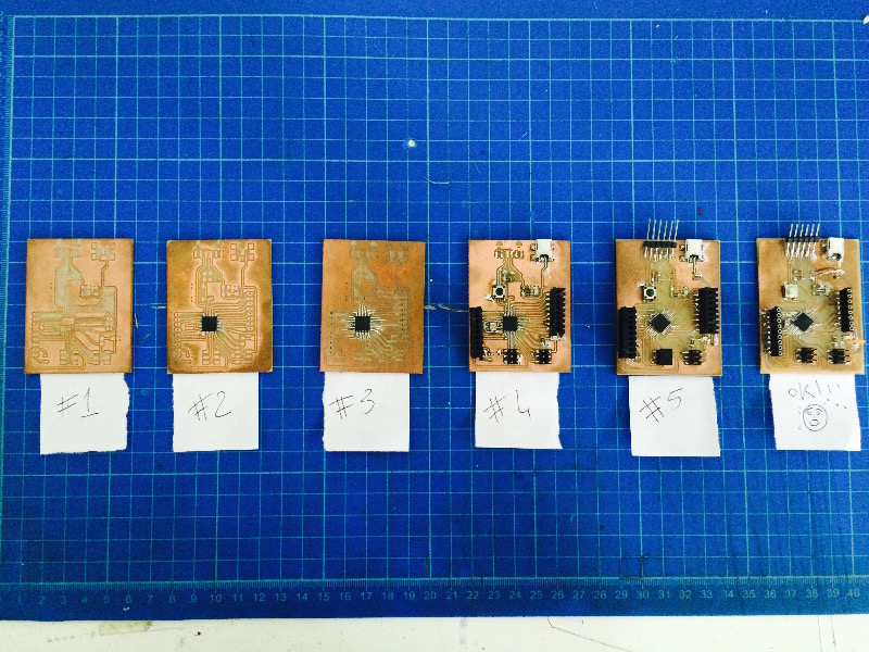
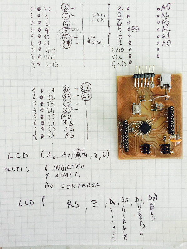
I created a card , a clone of the Arduino I called Rotomolduina . Rotomolduina has a ATtiny 328 , 6-pin and 8 -pin digital analog . It ' was really hard , I made the card for 6 times before being able to program it , the slopes were always very close to each other and often false contacts near the microcontroller were impossible to recover!
The advice I can give is to make sure the tracks " comfortable " to be welded at the risk of throwing away time , components and copper rods !
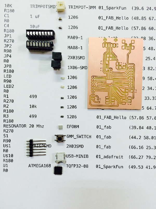
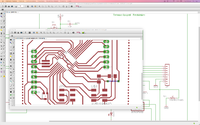
That's how it is composed Rotmolduina
10K TRIMPOTSMD TRIMPOT-3MM
C1 1uF
C4 10uF
JP1
JP2
JP4
JP8
LED
LED2
R1 99
R2 10k
R3 499
RESONATOR 20 Mhz
S1 6MM_SWITCH
U$1 AVRISPSMD 2X03SMD
U$10 USB-MINIB
U1 ATMEGA168 TQFP32-08
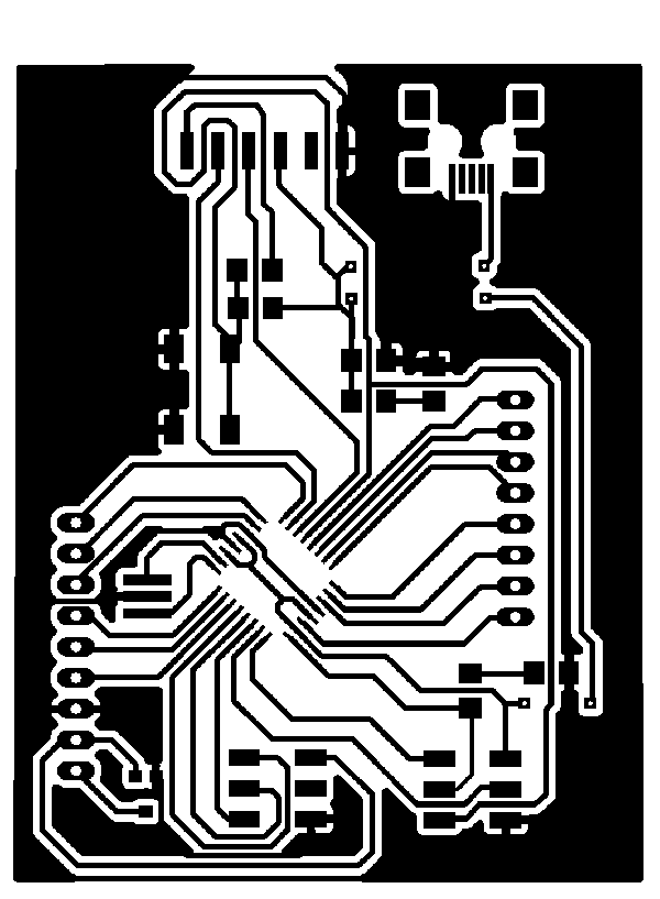
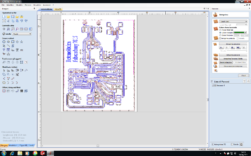
After working with Eagle and the rooting of the board, I exported the file as PNG to another resolution and imported the same file on Aspire.
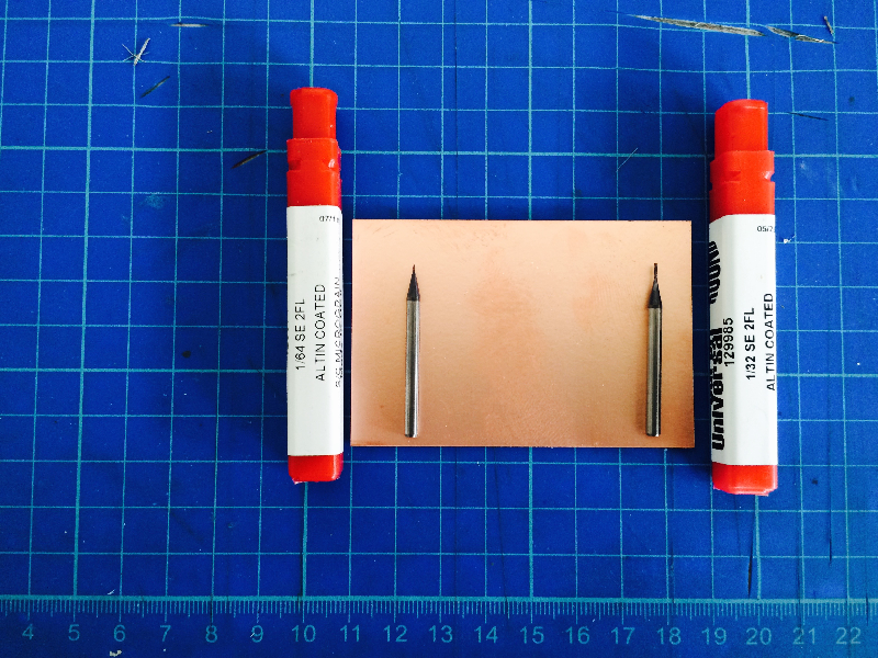
With Aspire I made modufiche necessary to ensure the passage of the cutter, with ores software thanks to the "Calculate" you can not figure out where to go and where to pass the cutter during machining, is set imprtante measures of the board and the measures of the tips . For this work I using the shell tips for feesatura 1/64 and 1/32 for cutting and holes. Aspire to the file is exported in text files, one file for each function, eg. one for cutting, one for milling etc etc ..
With text files, the cutter is used Mach 3, first of all placing the copper bar, then it is brought to 0 the Z-axis, consequently the axes X and Y, always making sure the right towards cutting. Mach 3 allows you to upload files in txt and thanks to a slider on the right side of the screen you can see the simulation work.
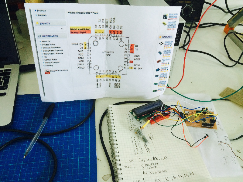
With the same system I made the keyboard to control the LCD monitor.
The first step was to run the ldc monitor , then I wrote a very simple program for Arduino , here follows the identification of pin :
/*
LCD 16 caratteri x 2 righe
pin del circuito LCD:
* LCD RS pin to digital pin 7
* LCD Enable pin to digital pin 6
* LCD D4 pin al digital pin 5 +
* LCD D5 pin al digital pin 4 +
* LCD D6 pin al digital pin 3 +
* LCD D7 pin al digital pin 2 +
* LCD R/W pin al ground
* LCD VSS pin al ground
* LCD VCC pin al 5V
* 10K pot
* ends to +5V and ground
* wiper to LCD VO pin (pin 3)
*************************
This is the program compoleto arduino , with engines and lcd monitor , at the bottom of this page you can scricare file Arduino to replicate the program.
pin dei tasti:
*Tasto indietro al digital pin 6
*Tasto avanti al digital pin 7
*Tasto conferma al digital pin 8
***********************************************
pin controllo motore posto in OUT A:
*pin controllo 1 al digital pin 10
*pin controllo 2 al digital pin 13
*pin enableA per la velocità al digital pin PWM 9
*/
// libreria dello schermo LCD
#include
//definizione dei pin dei tasti e del motore
#define pinMotoreA 10
#define pinMotoreB 13
#define pinMotoreE 5
#define pinIndietro 6
#define pinAvanti 7
#define pinConferma A0
//creo un carattere custom un blochetto tutto nero
byte blocco[8] =
{
B11111,
B11111,
B11111,
B11111,
B11111,
B11111,
B11111,
B11111
};
//definizione schermata iniziale
static char Intro0[15] = "OPEN";
static char Intro1[15] = "ROTOMOLDER";
static char Intro2[15] = "FabLab SPQwoRk";
//definizione schermata menu principale
static char Posizione1[15] = ">> Direction";
static char Posizione2[15] = ">> Velocity";
static char Posizione3[15] = ">> Program";
// inizializzazione dei pin dello schermo LCD
LiquidCrystal lcd(7, 6, A5, A4, A3, A2);
//variabili
int vel =0;
void setup() {
// dichiara il numero di caratteri e di righe del nostro schermo
lcd.begin(16, 2);
//attivo il nuovo carattere
lcd.createChar(0, blocco);
//definizione stato dei pin
pinMode(pinMotoreA, OUTPUT);
pinMode(pinMotoreB, OUTPUT);
pinMode(pinMotoreE, OUTPUT);
pinMode(pinIndietro, INPUT);
pinMode(pinAvanti, INPUT);
pinMode(pinConferma, INPUT);
//schermata di reset
for(int n = 0; n < 16; n++)
{
lcd.setCursor(n,0);
lcd.write(byte(0));
lcd.setCursor(n,1);
lcd.write(byte(0));
delay(50);
}
// schermata Principale
Intro();
Serial.begin(9600);
}
void loop() {
lcd.setCursor(0, 1);
int avanti=digitalRead(pinAvanti);
int indietro=digitalRead(pinIndietro);
int conferma=digitalRead(pinConferma);
if (avanti==HIGH || indietro ==HIGH || conferma == HIGH){
Menu();}
}
void Intro(){
lcd.clear();
lcd.setCursor(0,1);
lcd.write(" ");
for(int n = 0; n < 4; n++)
{
lcd.setCursor(n,0);
lcd.write(Intro0[n]);
delay(50);
}
lcd.setCursor(4,0);
lcd.write(" ");
for(int n = 0; n < 16; n++)
{
lcd.setCursor(n+6,0);
lcd.write(Intro1[n]);
delay(50);
}
for(int n = 0; n < 16; n++)
{
lcd.setCursor(n+1,1);
lcd.write(Intro2[n]);
delay(50);
}
lcd.setCursor(15,1);
lcd.write(" ");
}
void Menu(){
boolean PosizioneSelezionata = false;
int avanti=digitalRead(pinAvanti);
int indietro=digitalRead(pinIndietro);
int conferma=digitalRead(pinConferma);
lcd.setCursor(0,0);
lcd.write("SELECT VELOCITY ");
if(avanti==HIGH && vel-3){
vel++;}
else if(indietro==HIGH && vel>0){vel--;}
Serial.println("vel ="+ vel);
delay(500);
switch(vel){
case 0:{
lcd.setCursor(0,1);
lcd.write(" MOTOR STOP! ");
if (conferma==HIGH){
Serial.println("Fermo");
digitalWrite(pinMotoreA,LOW);
digitalWrite(pinMotoreB,LOW);}
break;}
case 1:{
lcd.setCursor(0,1);
lcd.write(" MEDIUM SPEED ");
if (conferma==HIGH){
Serial.println("Lento");
digitalWrite(pinMotoreA,HIGH);
digitalWrite(pinMotoreB,LOW);
analogWrite(pinMotoreE, 125);}
break;}
case 2:{
lcd.setCursor(0,1);
lcd.write(" HIGH SPEED ");
if (conferma==HIGH){
Serial.println("Veloce");
digitalWrite(pinMotoreA,HIGH);
digitalWrite(pinMotoreB,LOW);
analogWrite(pinMotoreE, 255);}
break;}
}
}
void drawMenu (int posizione)
{ switch ( posizione ) {
case 0:
{
lcd.clear();
for(int n=0;n - 16; n++)
{lcd.setCursor (n,0);
lcd.write(Posizione1[n]);
lcd.setCursor(n,1);
lcd.write(Posizione2[n]);
}
lcd.setCursor(12,0);
lcd.write(" ");
lcd.setCursor(11,1);
lcd.write(" ");
break;}
case 1: {
lcd.clear();
for(int n=0;n-16; n++)
{lcd.setCursor(n,0);
lcd.write(Posizione2[n]);
lcd.setCursor(n,1);
lcd.write(Posizione3[n]);
}
lcd.setCursor(11,0);
lcd.write(" ");
lcd.setCursor(10,1);
lcd.write(" ");
break; }
}
}
void SelezionaVelocita(){}
void SelezionaDirezione(){}
void SelezionaProgramma(){}
void MotoreDestra(){
digitalWrite(pinMotoreA,LOW);
digitalWrite(pinMotoreB,HIGH);}
void MotoreSinistra(){
digitalWrite(pinMotoreA,HIGH);
digitalWrite(pinMotoreB,LOW);}
void Velocita(int valVel){
analogWrite(pinMotoreE,valVel);}
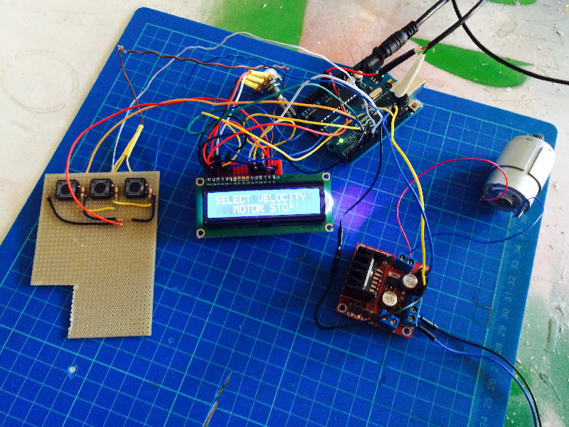
As soon as I finished the electronics , I connected all of a 12-volt DC motor , during the first test everything was going well , the program has responded very well , and the engine ran at speed control with 2 : MEDIUM and HIGT , then there is the option MOTOR STOP .
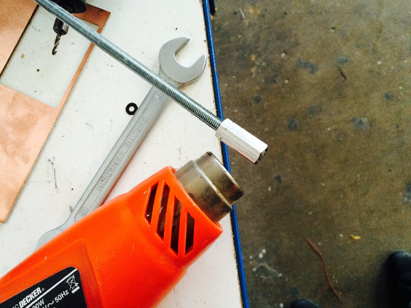
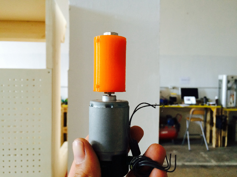
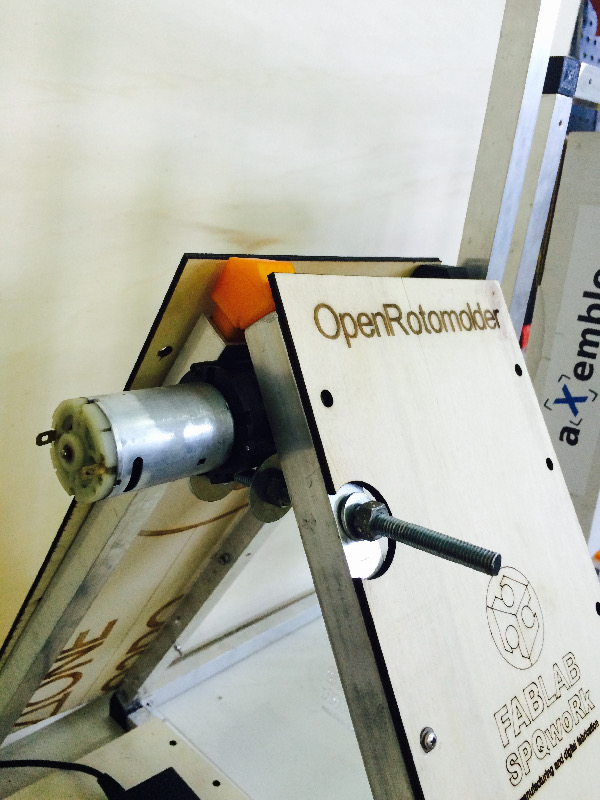
For transmits the speed to the frames of the rotomolding I prepared a 3d file that one side had the seat for the motor shaft , on the other instead I drowned a hexagonal nut 8 mm in thickness and 30 mm in length , this solution has proved weakness her when she was put to work by car , the engine was too weak , then the transmission of power was not the case .
I needed a more powerful engine !!!
In Fablab SPQwoRk I collect all waste technological and electronic arriving, because often there are parts still usable.
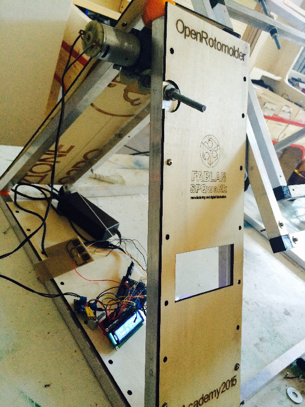
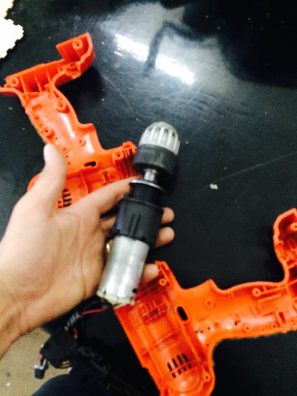
Initially I thought of using the engine of a venitlatore, but it was too cumbersome for the structure, he threatened to unbalance the whole one side. Among various things in the time I put aside various drills and screwdrivers with some flaws, I removed one, and I tulizzato its engine to give life to my Open Rotomolder. The drill brings a 14.4-volt DC motor, richeide for this power supply with 15/18 volt and an output of 4.3 amps, this solution proved to be a turning point for the entire project, because it allowed me to abdare forward and also finding a good solution for the transmission. I chuck using the shell of the same drill to keep blocked the threaded rod of the transmission, then I created a structure similar to the side to hold the rotomolding frezione engine and to hide what is not good to see by eye.
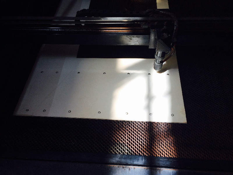
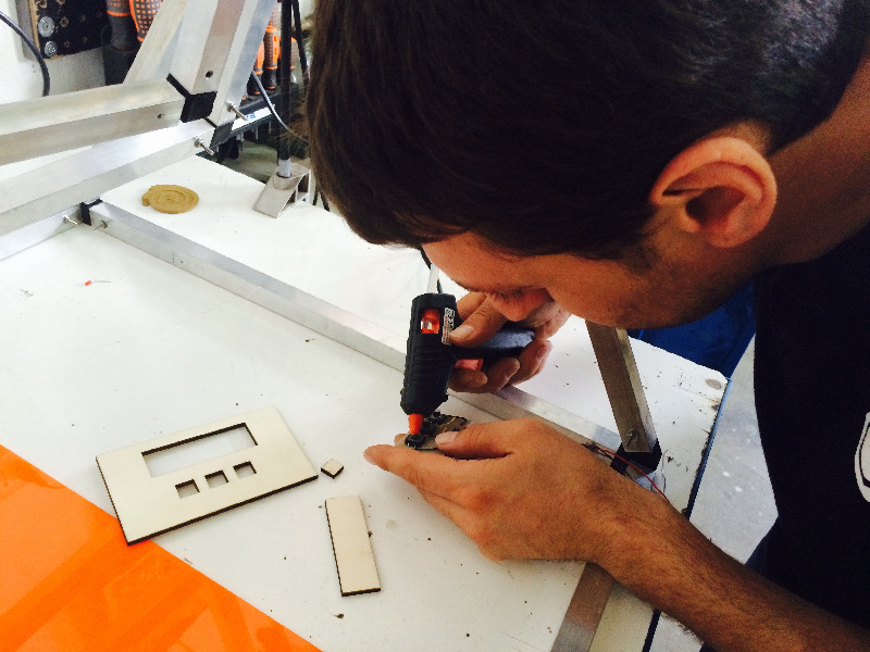
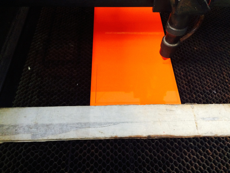
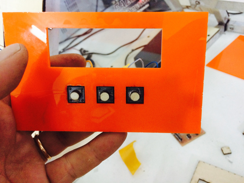
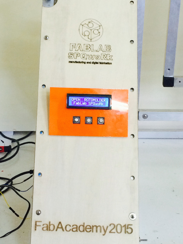
The engine cover is the natural continuation of the car , I did not realize that unenforceable lter another triangle aluminum pull to the outside of the machine . To hold together the body of the motor to the process I realized then that I 2D laser cut , using a plywood 0.4 mm thick , the bezel of the display which also houses the buttons I made of Plexiglas from 0 , 3 mm . All designs I made with Solid Works , then exported as a DXF file , this type of extension allows you to create a file pure and usable in many programs from the machine .
Laser cutting of plywood was performed with a power of 70 , 60 and corner power the Speed 10 , for the processing of Plexiglas instead using the shell I have a power of 80 , 65 corner power , speed 8 .