Electronics
To operate the machine, I designed a board that control the DC Motor with a desktop application. I started on a breadboard connected with a Satshakit running Firmata as in my week 14 exercise. On the breadboard I connected a 12Volts power source, a DC Motor and tryed different setups with different MOSFETs, diodes and capacitor. This process took me two days in which I understood what every component does and why.
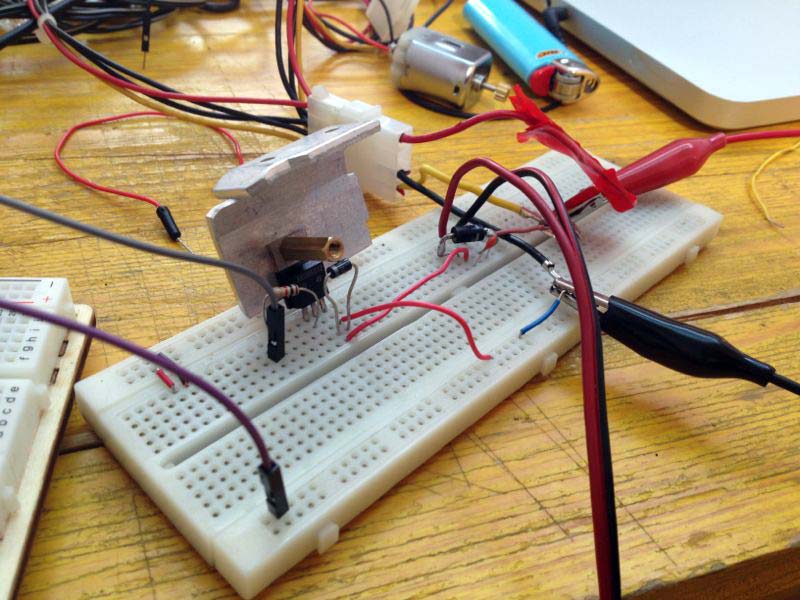
After my experiments I came out with a setup including:
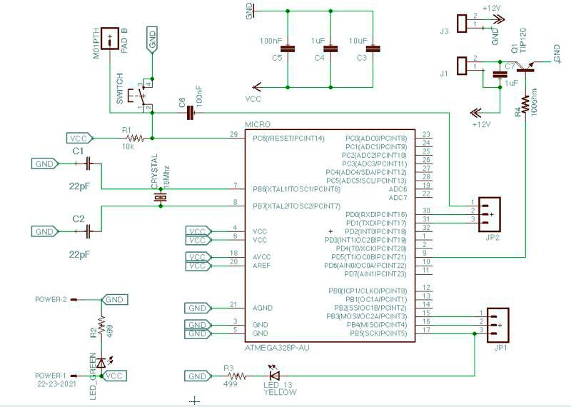
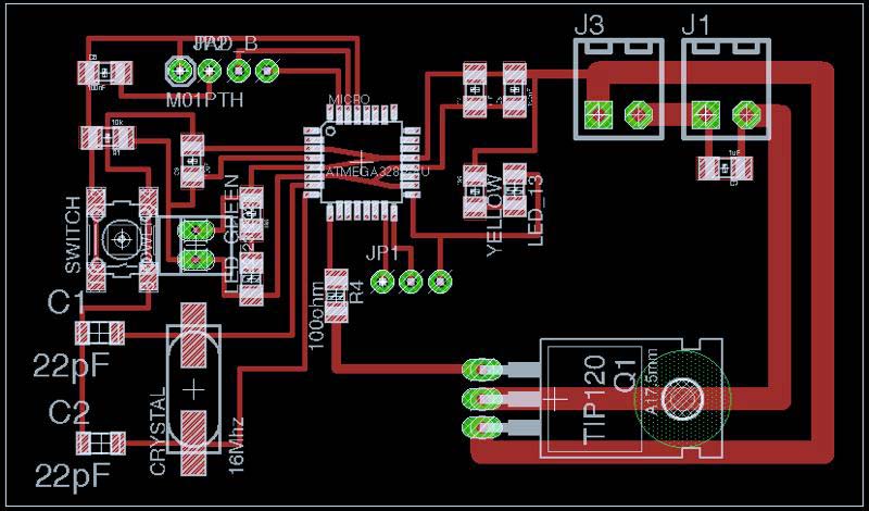
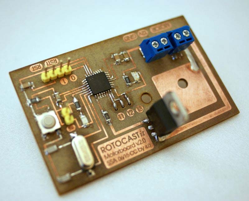
On Eagle I designed the board starting from the Satshakit file, I removed all the pin I didn't need and added the mosfet, the connectors for the 12volts power source and the motor, the capacitor of the motor and the transistor between the Atmega and the MOSFET.
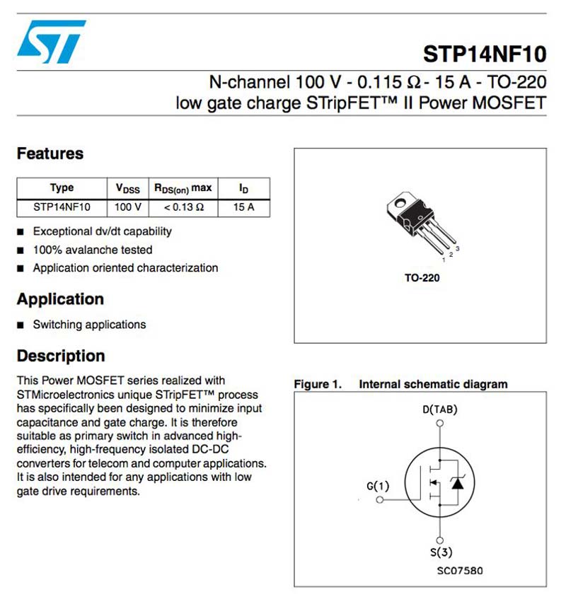
On Eagle I couldn't find the same MOSFET I wanted to use, so I used a TP120 which has the same package of the STP14NF10 (TO220 package).
Then I imported the png image in Inkscape and added the graphics to remember the pin number, the name and I draw a large area that will work as heat dissipation.
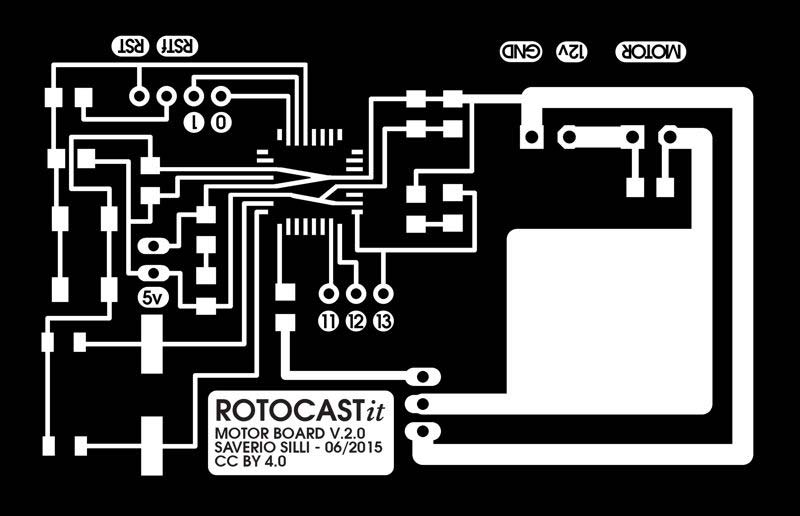
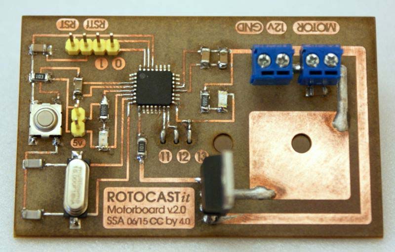
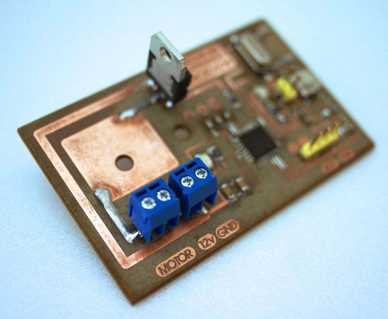
While soldering the pins 11-13, I made a mistake and the copper plate plied away, so I had to reverse the connectors which now emerge from the backside of the pcb.
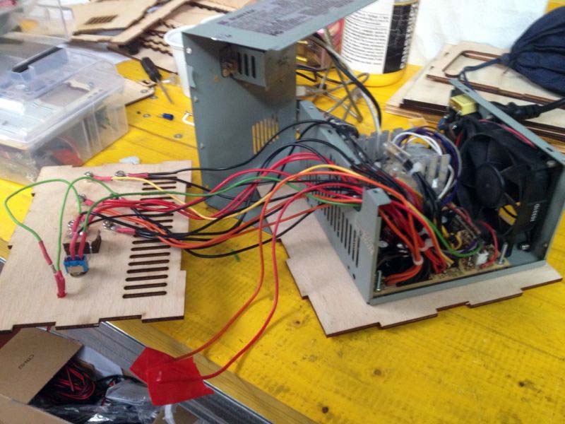
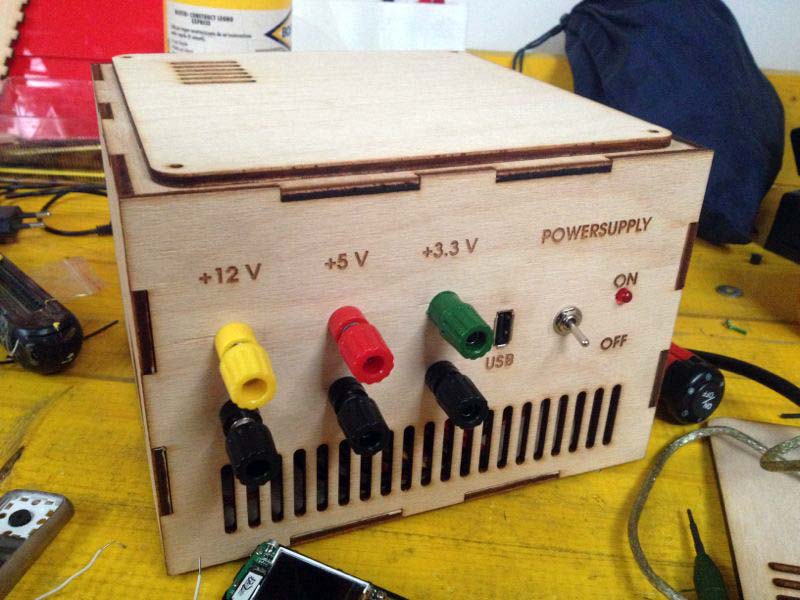
In the spare time I also built a bench power supply from a reclaimed computer ATX power supply with 12, 5 and 3,3 Volts connectors, GND and USB connector and an On/Off switch with LED. Making it is very easy, you only have to short circuit the green cable with one GND in the main socket, lasercut a simple box and the rest is just embellishment. I will use to power up the machine connecting my board to the 12 Volts and GND output of the power supply box.