WEEK 6
06. Electronics Design
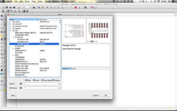
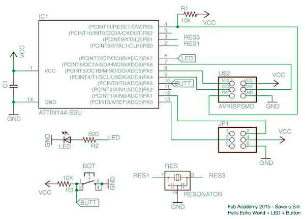
This was my first time ever dealing with electronics design, but the task has been made much easier thanks to Simone Boasso's great lecture about electronics and Eagle. I spent a whole sunday working with Eagle and at the end of the day I came up with tha schematics for the Hello Echo World + Button + LED board.
Board design with Eagle
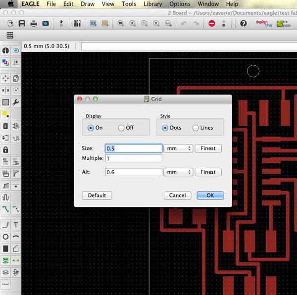
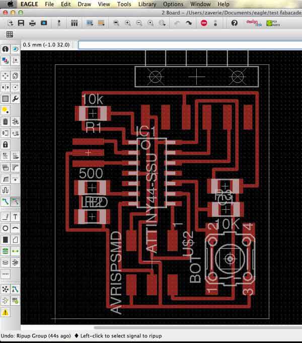
Moving to board design I first arranged the parts nice and clean, then I set the grid to a 0,5 mm spacing to easily place the parts
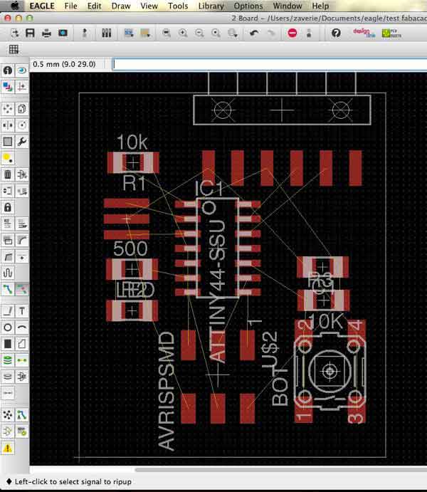
In the first time I went with Autotracing, but I wasn't satisfied with the results, even if the efficiency was 100% the traces looked very messy and with no "style". I traced the routes by myself and I found it very fun and challenging.
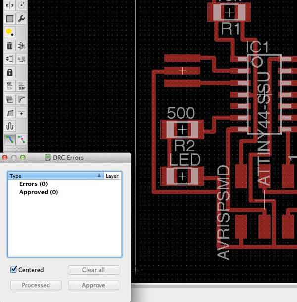
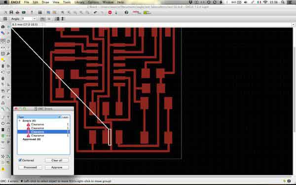
I run the design rule check and it showed some critic points where the wires where too close. I took note of these to work them in Photoshop.
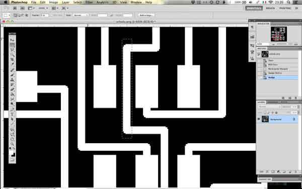
Refining with Photoshop
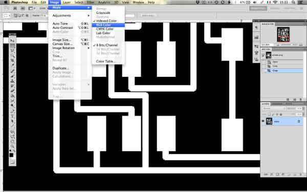
After exporting the png I worked on those critical points with Photoshop. While I was there I also moved many other lines just for the love of beauty. Note that in Photoshop, to work with the png created with Eagle, you have to switch to RGB Color in Image>Mode
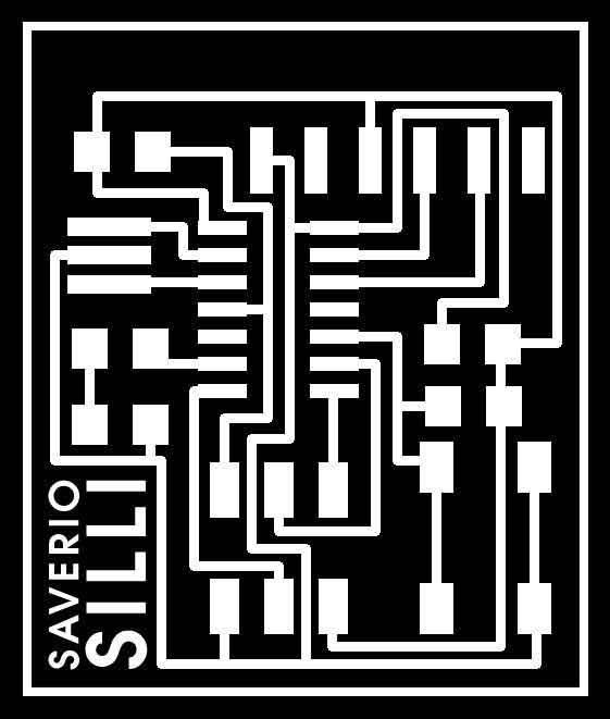
I added my name and a border to the board in Photoshop, then moved to Illustrator. Since we are using a Fibre/CO2 Laser Cutter I mixed the monochrome image which will be engraved with a vector rectangle to cut out the board.
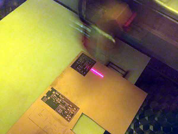
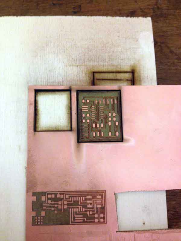
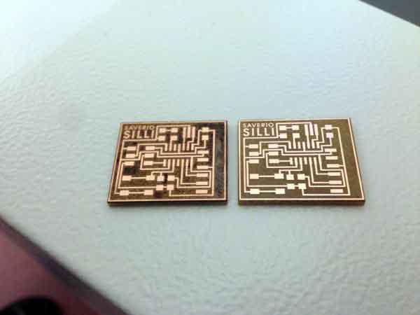
PCB's laser engraving and cutting
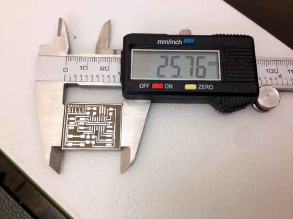
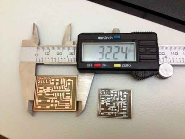
On the Trotec Laser Cutter we had to experiment the settings of the laser as it was one of the first times working with PCBs. This is the final settings we tried as they made a nice and clean job. The first board had a way too high power and we "cooked" the resin. Another issue was the size of the board. I discovered after making two of them that they were smaller. The problem was that Illustrator (which I used on my computer to create the SVG) and Inkscape (which we used on the laser cutter's computer to send the print) dealt with different resolution. So I scaled the file to the right size on Inkscape and the final result looks very good.
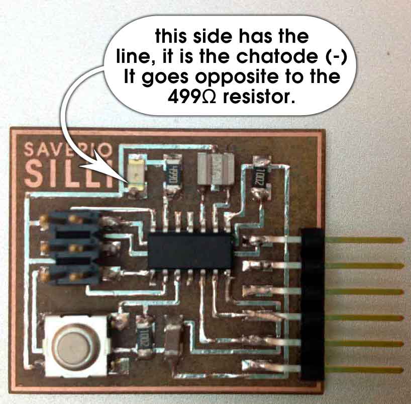
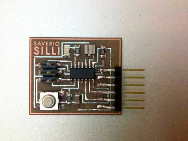
Soldering
Now on to soldering. It was my second time with solder and it went pretty smooth. The only hesitation was about the polarity of the LED. The side with the line (if you manage to see it) is the Cathode (+) and it goes opposite to the resistor. As with the Fab ISP I first put flux on the board and then soldered all over the board just to wet the wires. Even if it helps when soldering the components, the final look is terrible and I wouldn't do it again.
Schematic, board and cut files are available here: