Week 13
Networking and Communications
NETWORK CONNECTING
Assignment: Design and build a wired and/or wireless network connecting at least two processors
networking_communications/index.htmlGoal: The aim of this assignement is to network several boards together in the form of a serial bus. The bridge board is connected to a computer with a FTDI cable, the two node boards are connected to the bridge board.
TUTORIAL: networking_serial_bus.html
I used: 1 Hello.bus.45.bridge and 2 hello.bus.45.node.
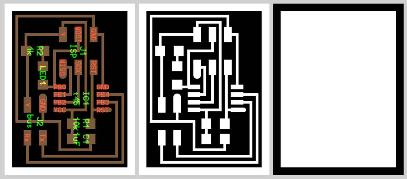
At the beginning, I downloaded the .png files for milling 2 nodes and 1 bridge. The only difference between the boards is that the bridge has 6 extra pins for connecting to the FTDI cable, while the nodes have only a 4 pin header to communicate. The brigde gives power to other nodes.
BRIDGE: Hello.bus.45.bridge

COMPONENTS:
- 1 Attiny 45
- 1 Header 6 pins
- 1 Header 4 pins
- 1 Header FTDI 6 pins
- 1 Red Led
- 1 Resistor 1 K
- 1 Resistor 10 K
- 1 Capacitor 1 uf
NODES: hello.bus.45.node

COMPONENTS:
- 1 Attiny 45
- 1 Header 6 pins
- 1 Header 4 pins
- 1 Red Led
- 1 Yellow Led
- 1 Resistor 1 K
- 1 Resistor 10 K
- 1 Capacitor 1 uf
MILLING - WELDING:
Tools: Roland MonoFab SRM20
Table size (LxP): 232.2 x 156.6 mm
Distance from collet tip to table: 232.2 x 156.6 mm
- DIA 0.0156" DIA 2FL SE AlTiN 1/64(engraving)
- 0.0312" DIA 2FL SE AlTiN 1/32(milling)

PROGRAMMING:
To program the board you can use hello.bus.45.c code and the makefile as reported in the Fab Academy website. You have to program the C code for each board. Each node, in fact, needs a different node id number.
So, the hello.bus.45.c has to be downloaded and modified three times: one time to flash the bridge board, the second and third time to flash the node boards.
- In the C code, define node_id '0' and save the file. Then you have to connect the bridge board to computer with the FTDI header and program it using the USB programmer. Then flash the bridge board as node 0: sudo make -f hello.bus.45.make program-usbtiny.
- Then take another node board, modify the C code, define node_id '1' and save the file. Use the bridge board "0" to power node boards and connect them to TX and RX. Then flash the node board as node "1": sudo make -f hello.bus.45.make program-usbtiny.
- In the C code, define node_id '2', and repeat the process.


COMMUNICATIONS:
To let boards to communicate, you have to connect them with the computer and among themselves, then you have to enter 0-1-2 into serial monitor and press the send button.

- Connect the boards and plug the bridge board to the computer with a FTDI cable.
- Connect them to Tx and Rx and flash the first node board as node 1.(type in terminal: sudo make -f hello.bus.45.make program-usbtiny).
- Repeat the same thing for the second node board as node 2.
- Open the Arduino IDE and go to Tools>Serial Monitor to open the serial monitor. Into the serial port enter the number of a node and "send" it. After all the LEDs light up once, the board that corresponds to the number that is entered into the serial port, should light up again.
-There's a problem with node 2, a lot of noise, so the returned value is not clear.
Notes:
- Make sure the baud rate is set to 9600;
- Each board needs to have a different node id;
- Problems with noise of nodes. Using the Arduino serial monitor the nodes name showed was unusual. I checked the solder points, changed the connectors and rolled the wires. In this way i was able to have a cleaner output.
Download:
hello.bus.45.bridge.interior.pnghello.bus.45.bridge.interior.rml
hello.bus.45.bridge.png
hello.bus.45.bridge.traces.png
hello.bus.45.bridge.traces.rml
hello.bus.45.node.interior.png
hello.bus.45.node.png
hello.bus.45.node.traces.png
hello.bus.45.c
hello.bus.45.make