Week 11
Output Devices
OUTPUT DEVICES - MICRO SERVO SG90
Assignment: Add an output device to a microcontroller board you've designed and program it to do something
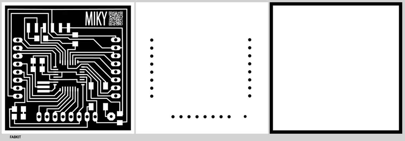
output_devices/index.htmlOnce again I tried to design a shield that could be useful for my final project.
Tools:
- Roland MonoFab SRM20
Table size (LxP): 232.2 x 156.6 mm
Distance from collet tip to table: 232.2 x 156.6 mm
- 0.0312" DIA 2FL SE AlTiN 1/32(milling)
MIKYFABKIT: microcontroller board

Components:
- 1 Resistors 10K
- 2 Resistors 499
- Yellow Led
- S1 switch 6mm
- 2 Capacitors 0.1 UF
- 1 Capacitors 1 UF
- Header 6 Pin
- Resonator 8MHZ
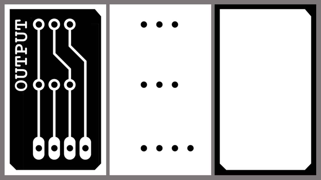
OUTPUT: SERVO MOTOR
I have chosen the Servo motor because I would like to apply this output device in my final project. I want to create a mechanical movement based on that. My intention is to move a surface according to inputs such as light, sound and humidity.
Components:
- Micro servo SG90 9G TOWERPRO
- Trimpot 10K with Knob
- Header 4 Pin
EAGLE:

PHOTOSHOP:

MILLING - MONOFAB SRM-20:
SETTING MACHINE:
- Open fabmodules.org
- Click on Input Format;
- Choose Image(.png) and Upload Image;
- Click on Output Format and choose "Roland Mill (.rml)";
- Machine Settings;
- Machine: SRM-20; Speed: 4; Jog: 1; Xmin: 0; Ymin: 0;
- CLick on Process and choose "PCB traces(1/64)" or "PCB outline(1/32)";
- Change offset to 5 (this is a personal setting);
- Hit Calculate;
- Save.

Instructions:
- Turn on the machine for the heating, at least for 20 minutes.
- Open the Fab Modules on a browser (fabmodules.org) and on the new window selected the endmill settings as 1/64".
- Click on the “load" button and selected the file (mine was simply OUTPUT1.png) and then set the machine type as SRM20. Press calculate. Fabmodules generates .rml file.
- When the machine is ready, open Roland Vpanel. Load the .rml file.
- Set the X,Y,Z axes.
- Now you can mill.
- To cut the board a 1/32th n-mill is needed, change the drill tool to the 1/32" on the Fabmodules.org, and repeat the process.
- Open again Roland Vpanel. Load the new .rml file.
- Set only Z origin.
- Repeat the same operation for every file.
PROGRAMMING:
I designed the board to place a potentiometer (Trimpot 10K with Knob). After various tests, however, I realized that the potentiometer I had available was defective. So, to save time, I simplified the output, using only the servomotor. In any case, the board is still designed to accept the potentiometer.

Arduino Sketch to program the microcontroller.

The output board worked as expected.