Week 10
Input Devices
INPUT DEVICES - lIGHT (PHOTORESISTOR)
Assignment: Measure something - add a sensor to a microcontroller board that you've designed and read it.
input_devices/index.htmlFor this assignment, I tried to design a shield that could be useful for my final project.
Tools:
- Roland MonoFab SRM20
Table size (LxP): 232.2 x 156.6 mm
Distance from collet tip to table: 232.2 x 156.6 mm
- 0.0312" DIA 2FL SE AlTiN 1/32(milling)
Tutorial:
input_device_examples_C.html
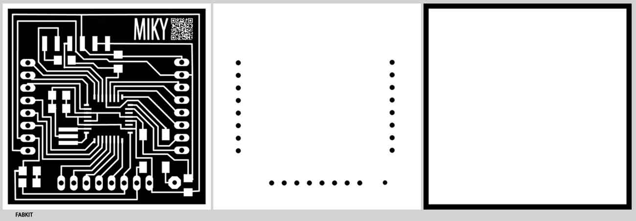
MIKYFABKIT: microcontroller board
I choose to use the FABKIT to read the sensor.

Components:
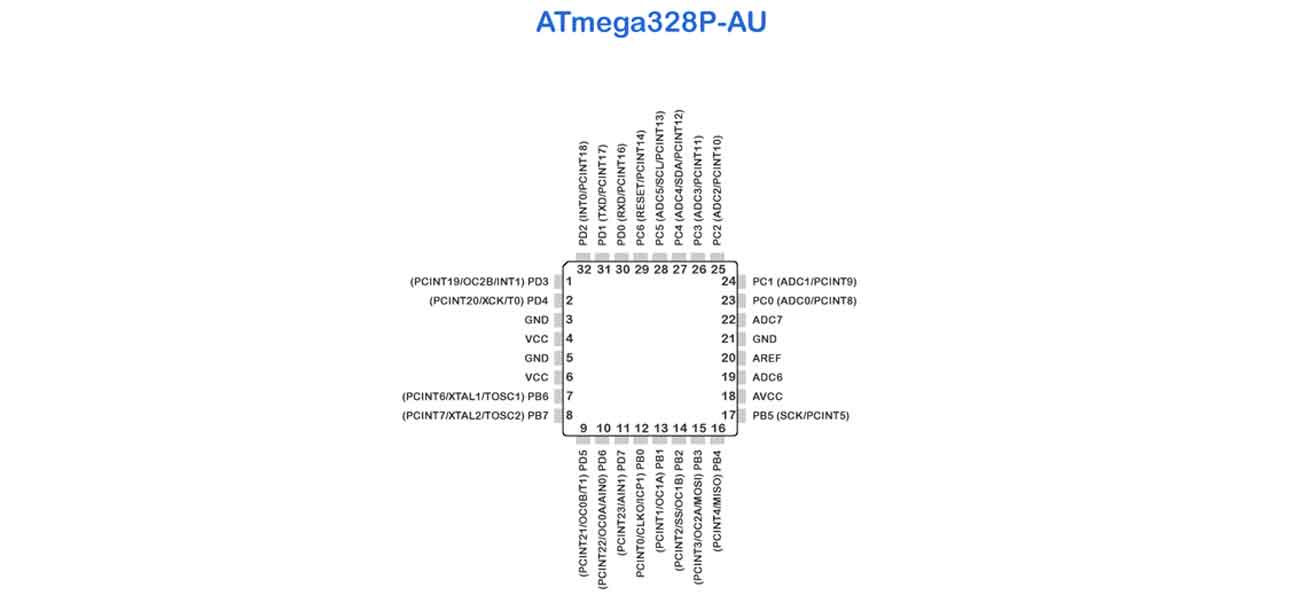
- ATmega 328P-AU
- 1 Resistors 10K
- 2 Resistors 499
- Yellow Led 1206 SMD
- Switch Button
- 2 Capacitors 0.1 UF
- 1 Capacitors 1 UF
- 1 Capacitors 10 UF
- Header 6 Pin
- Resonator 8MHZ

INPUT: Photoresistor CDS LDR
As my final project is a wall responding to humidity, light and sound, I decided to experiment Photoresistors as input devices.
Photoresistors (also know as light-dependent resistor) are a particular kind of variable resistors capable of change their resistance proportionally to the incident light intensity.
A photoresistor has a resistance which decreases in the presence of light. As the microcontroller ADC read voltage variations, it's necessary to use the photoresistor with a voltage divider.
Inserting it in a resistive divider in the "high" branch (the one toward the power supply) and a 10Kohm reference resistor toward ground, we get that the voltage across the second resistor increases according to the light hitting the photoresistor. Inverting the position of the two elements makes the circuit work in reverse. The 10kohm value for the fixed resistor is a conventional one.
EAGLE:
Eagle, produced by Cadsoft, is one of the most simple and powerful software for the design of electrical diagrams and PCB.
EAGLE downloading
Components:
- Resistors 10K ohm
- Header 3 Pin
- Photoresistor CDS – LDR GL5537-1
PHOTOSHOP:

MILLING - MONOFAB SRM-20:
SETTING MACHINE:
- Open fabmodules.org
- Click on Input Format;
- Choose Image(.png) and Upload Image;
- Click on Output Format and choose "Roland Mill (.rml)";
- Machine Settings;
- Machine: SRM-20; Speed: 4; Jog: 1; Xmin: 0; Ymin: 0;
- CLick on Process and choose "PCB traces(1/64)" or "PCB outline(1/32)";
- Change offset to 5 (this is a personal setting);
- Hit Calculate;
- Save.
Instructions:
- Turn on the machine for the heating, at least for 20 minutes.
- Open the Fab Modules on a browser (fabmodules.org) and on the new window selected the endmill settings as 1/64".
- Click on the “load" button and selected the file (mine was simply INPUT1.png) and then set the machine type as SRM20. Press calculate. Fabmodules generates .rml file.
- When the machine is ready, open Roland Vpanel. Load the .rml file.
- Set the X,Y,Z axes.
- Now you can mill.
- To cut the board a 1/32th n-mill is needed, change the drill tool to the 1/32" on the Fabmodules.org, and repeat the process.
- Open again Roland Vpanel. Load the new .rml file.
- set only Z origin.
- Repeat the same operation for every file.

SOLDERING:

PROGRAMMING:
Arduino Sketch to program the microcontroller.
The Sketch initializes the serial connection, reads the value of analog pin (A0), and saves it into sensorValue variable. Then it sends the string "sensor =" to the serial monitor of Arduino, and then the value of sensorValue. After that it stops for one second and then restarts.
Sketch-Photosensor
int sensorValue = A0;
void setup() {
Serial.begin(9600);
}
void loop() {
sensorValue = analogRead(A0);
Serial.print("sensor = " );
Serial.println(sensorValue);
delay(1000);
}

The programming of my board was successful, the data on the serial monitor did change accordingly with the light sensor.