_WHAT IS IT
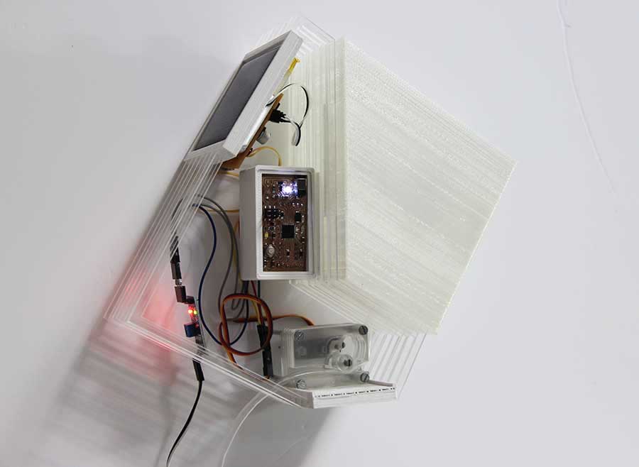
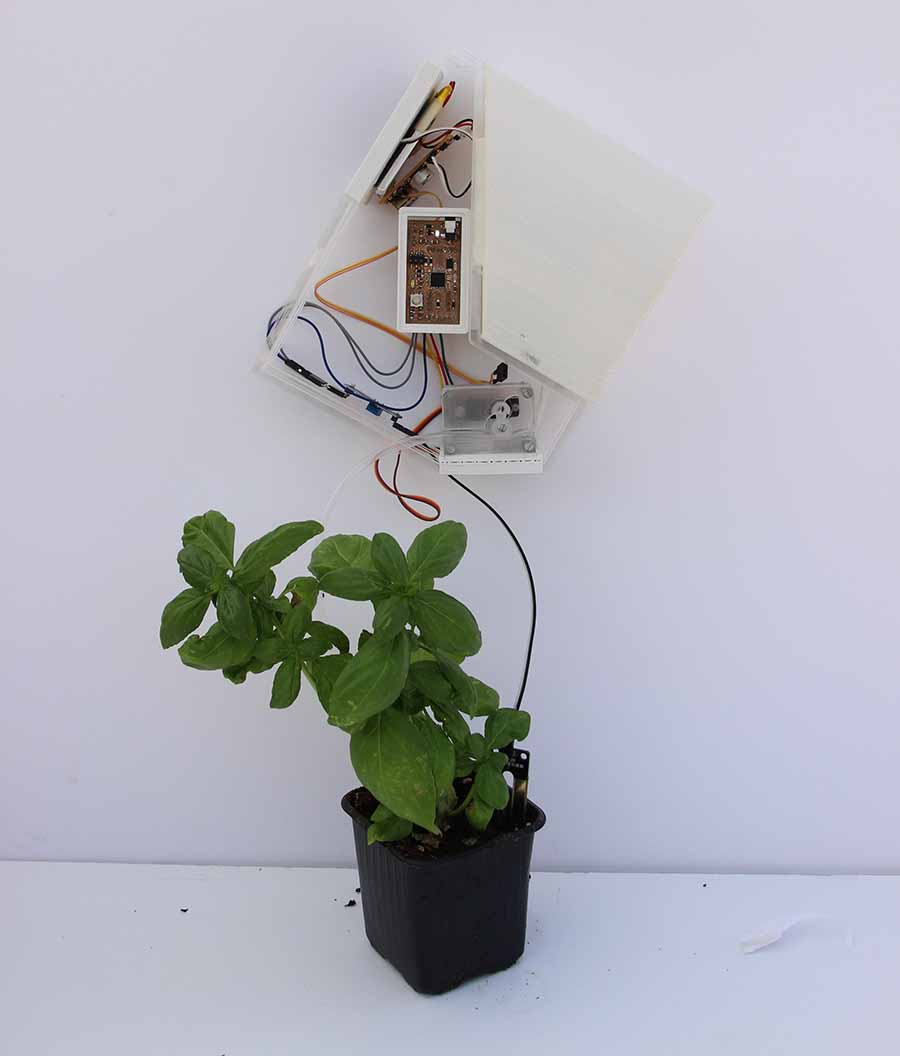
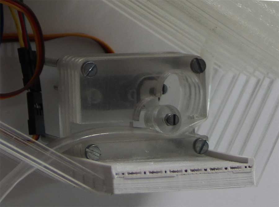
The project is a watering system which can be situated indoors or outdoors. It consists of an acrylic kit which works as the nest for a system of 3d printed cases containing the controlling parts, such as the electronics, and a water container that needs to be waterproof. Finally also inside this nest, a small water pump moved by a servo controls the water flow according to humidity values.
Having this two separated systems the user can customise the kit according to water amount that a certain plant needs and the orientation of the sun.
The whole system is powered by solar energy for it can be programmed and will automatically work in case of absence.
Although the programming is very easy, is the crucial part as it involves a direct interaction between the user and its plants. The user will need to know at which values of humidity a specific plant works better with.
_PROCEDURE
Milling the boards, making sure the circuit works
3d printing the cases containing the electronics
Laser Cut the acrylic nest
Programming
_MATERIALS AND PRICES
Methacrylate, for the size if this kit: €15
ABS filament: around €25 the roll, I used 65gr = €7
Solar Panel: I recycled one I had, around €10
Humidity sensor = €1,60
Barduino components around €10
TOTAL: €43
_HOW DOES IT WORK
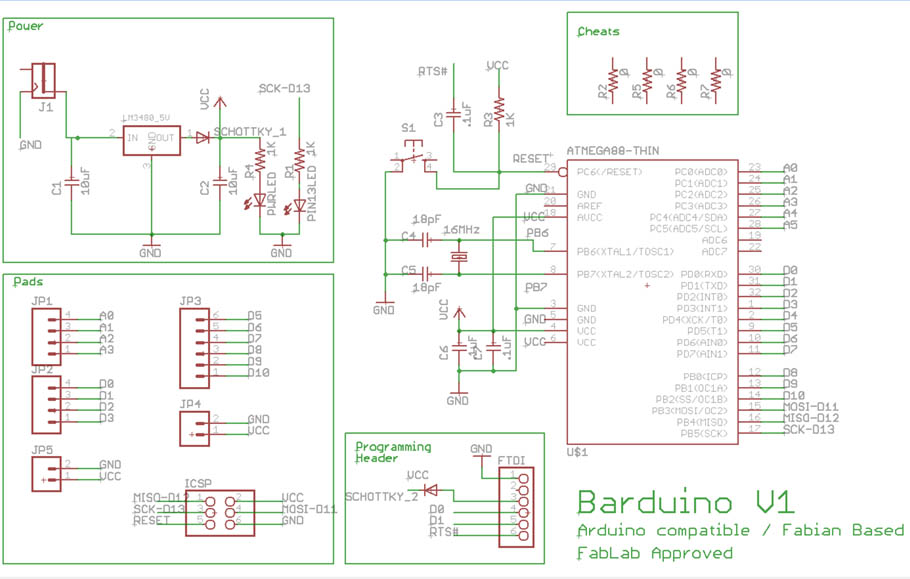
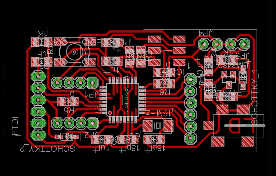
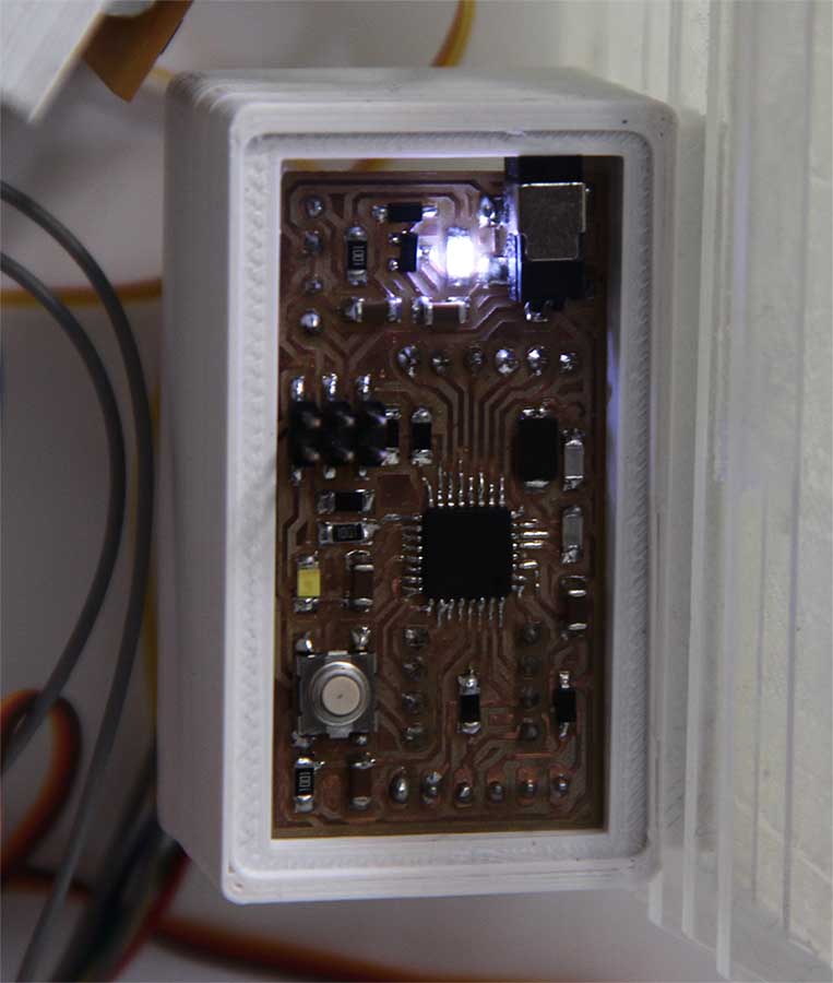
ELECTRONICS_ The electronic system consists of a barduino, which can be easily done in any local lab and works with Arduino IDE, an open source electronics software. I chose to use barduino because of the fact that with only one system it could be possible to control several kits.
This is a very precise tutorial on how to get started with Barduino, the components inventory, and the eagle files, schematic and board.
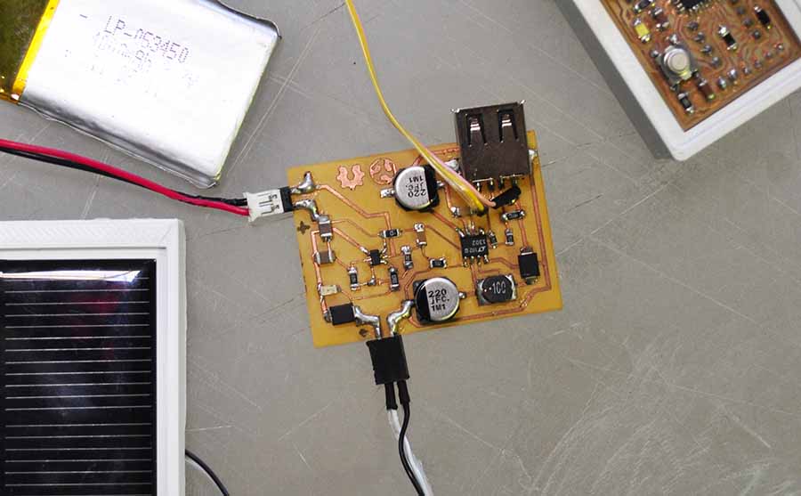
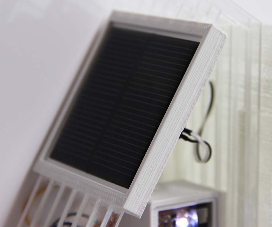
To power the microcontroller and the whole system, the kit has a 60x60, 5V solar panel which in my case I recylced it from a lamp I had. The first attempt to power the system was done completely different.
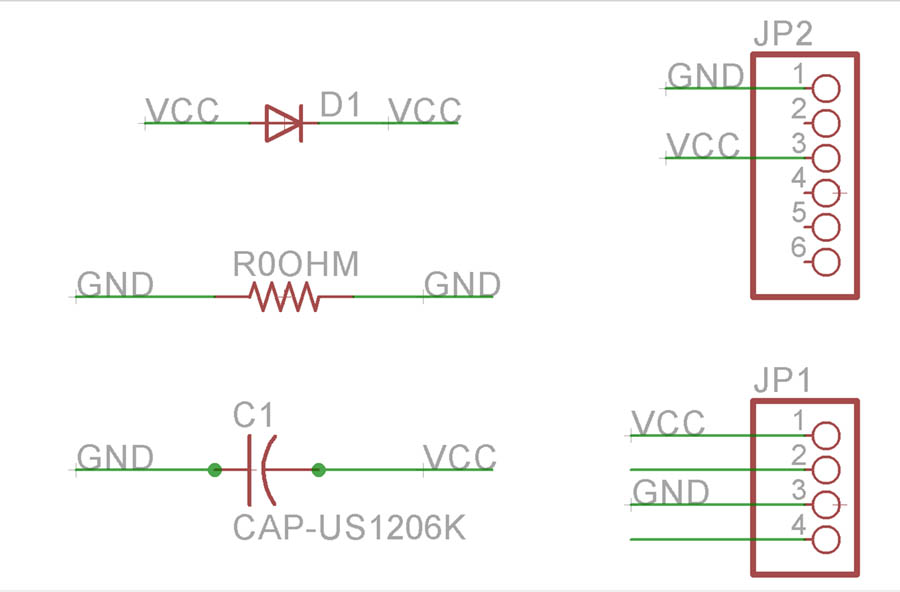
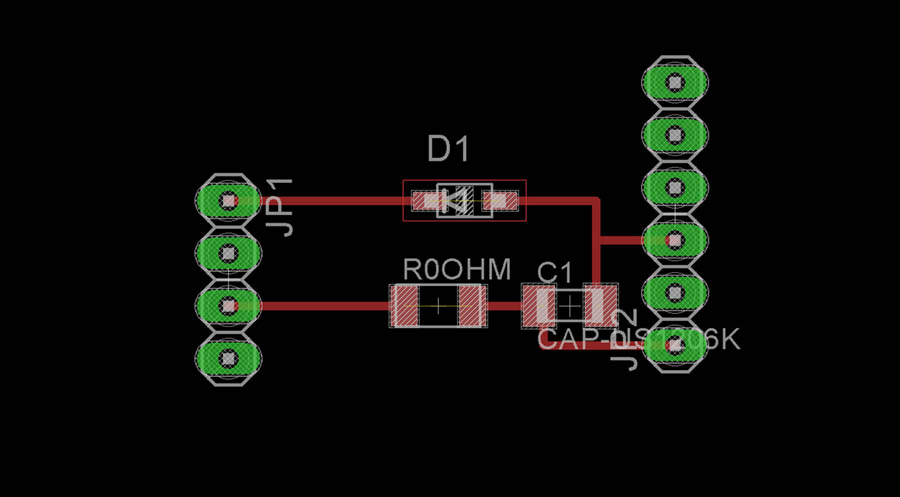
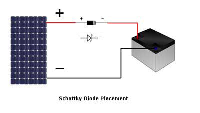
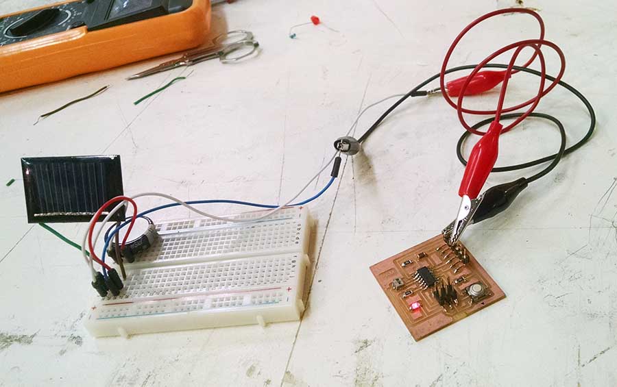
I started first with a 20x50 solar panel which was charging a 5.5v supercapacitor. For this I made a tiny board which was working as a shield for the barduino. The idea of using a supercapacitor was to take advantage of the fact that is a more direct system that with a LiPo battery for example. Besides, I added a schottky diode 100v to prevent the energy flow from going back to the solar panel and discharge the supercapacitor.
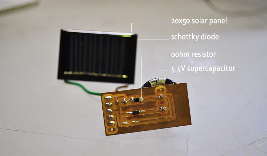
tests on how much can the solar panel can charge and transmit to the supercapacitor 5.5V: takes 10min to charge from a 9v power supply, enough to feed the barduino and move the servo motor a few times.
25mA is the maximum current the supercapacitor takes through the solar panel (20x50mm) with a 0 ohm resistor.
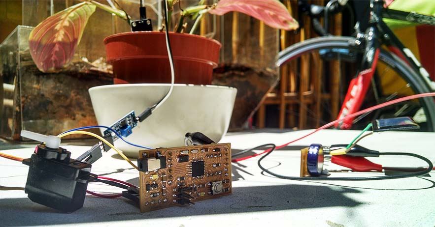
When i laid the whole system in the sun for a few hours, only the humidity sensor power led was turning on and the servo was not moving at all. As soon as I disconnected the servo the barduino power led turned on. This is evidencing that the power transmitted by the solar panel is not enough to feed the servo. So the next step was removing the 220 ohm resistor and replacing it for 0ohm resistor.
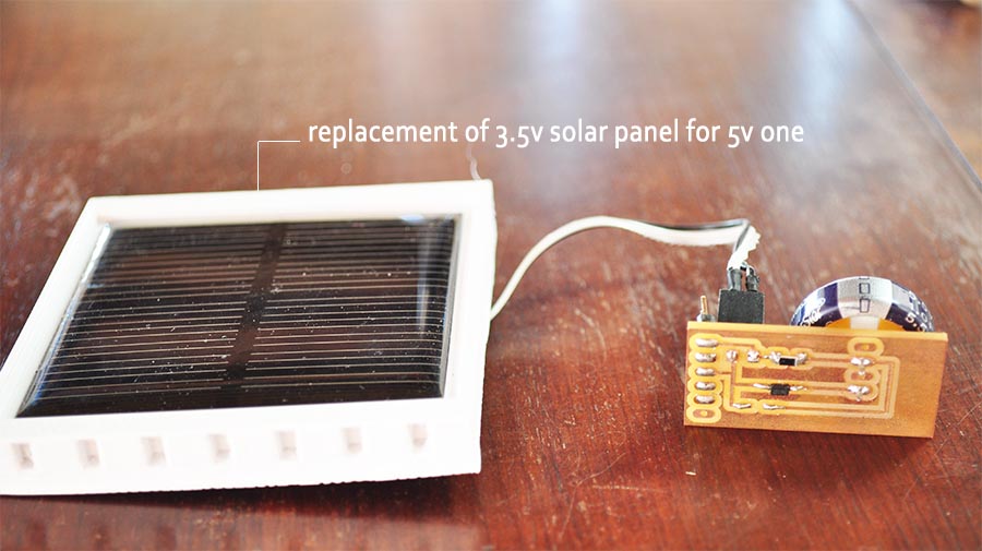
After all this changes the only possibility to give more power to the circuit was changing the source, so I removed the 35x25mm solar panel and changed it for a 60x60mm solar panel
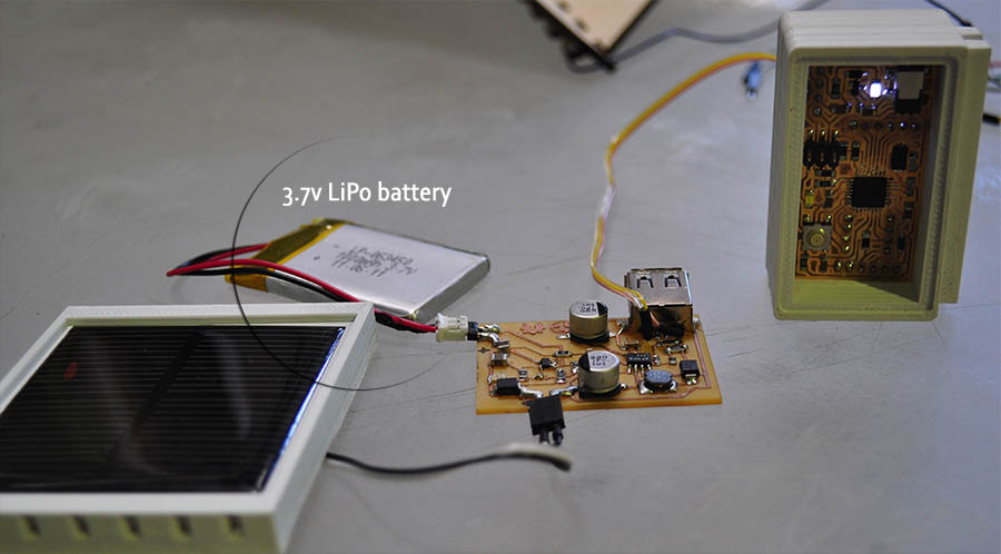
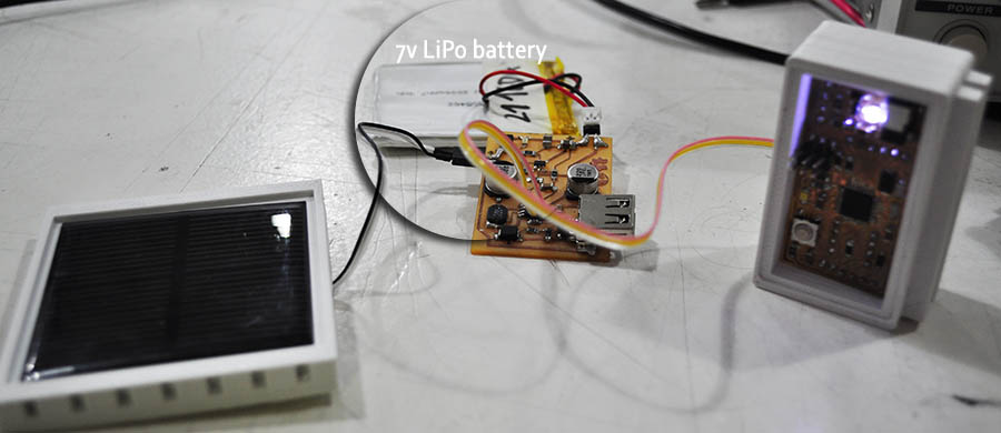
Finally, after the servo was not working, I decided to change the supercapacitor for a LiPo battery, and for this you need a whole new electric circuit. I first tried with a 3.7V LiPo battery, but although it was enough power for the servo to run, there was a lot of energy loss on the way. So, the best option is a 7v battery, which charges only to 3.95V due to the capacity of the solar panel chosen but the whole system runs perfectly.
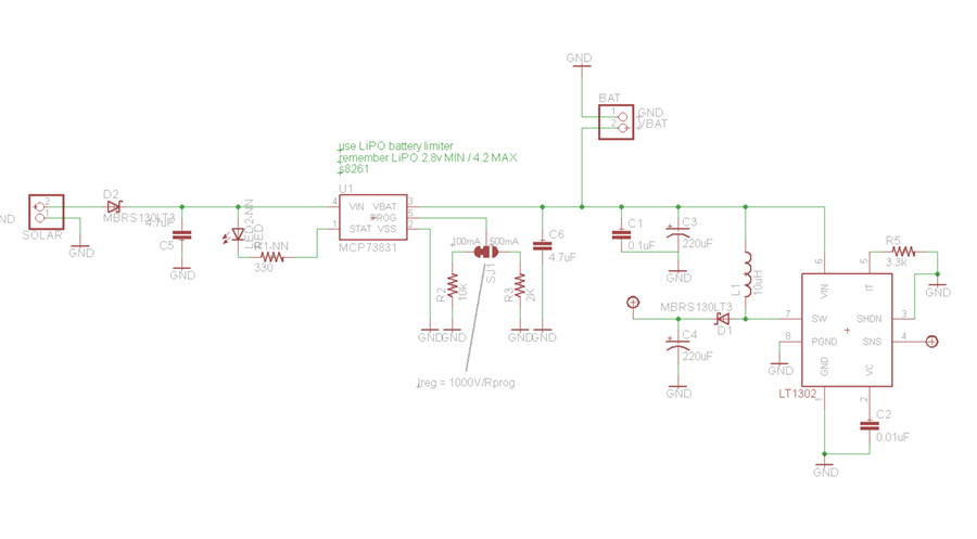
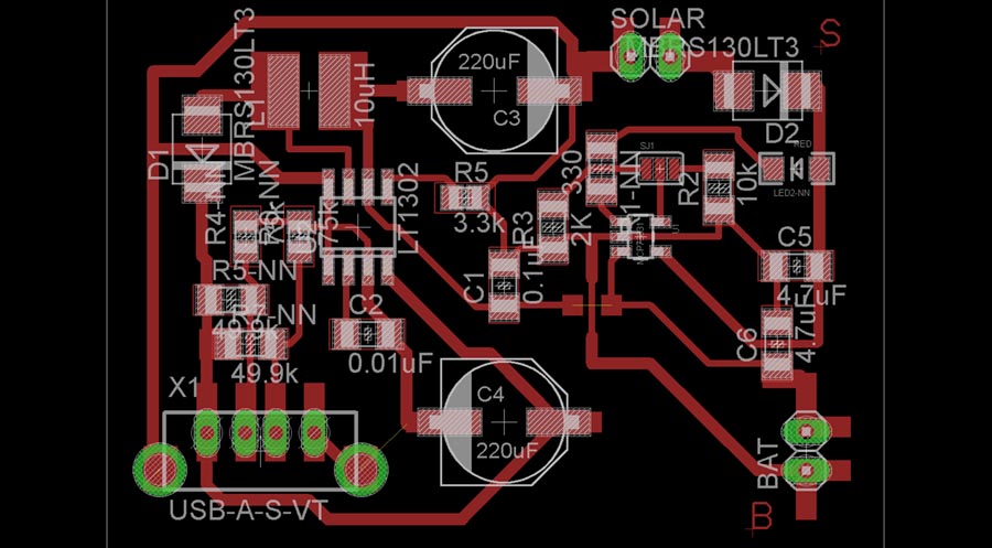
As I said, this needs another board to get the power from the solar cells to the LiPo battery. This is the files for the solar charging system:
Solar charging board
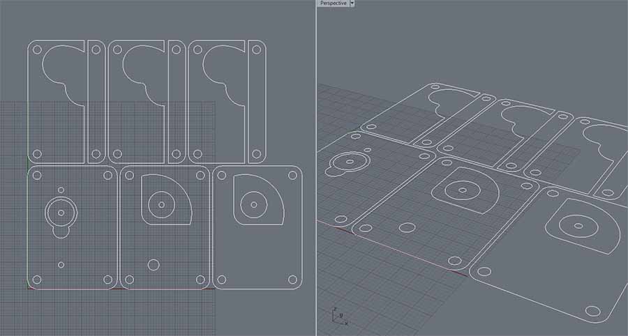
_3D PRINTING
The first step to biuld the kit is 3d print the cases that will contain the solar panel, the case for barduino and the joint holding the water pump. All of the were designed with little 3mm ditches to hold the acrylic parts. Finally, the water container is also 3d printed to prevent water flow from touching the electronic circuit. This last has 2mm thickness walls which gives it flexibility.
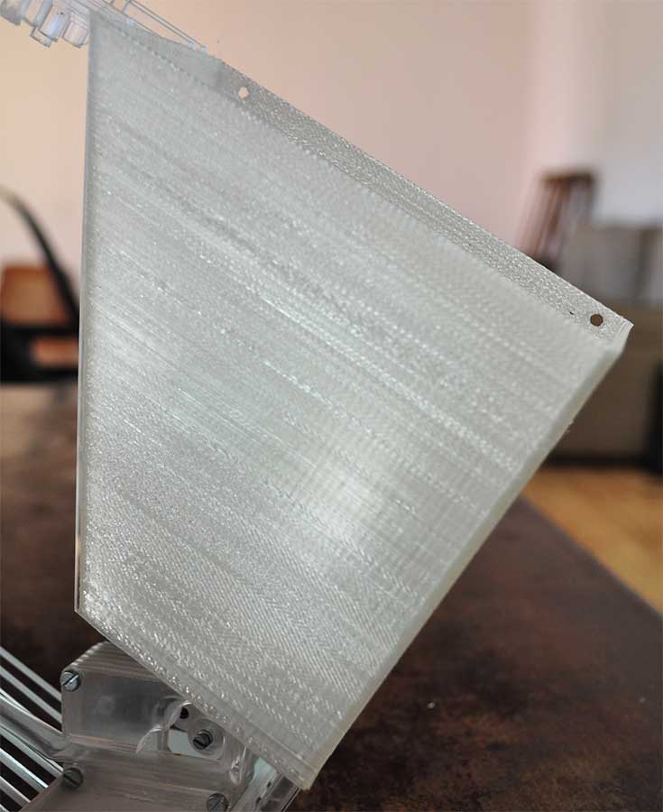
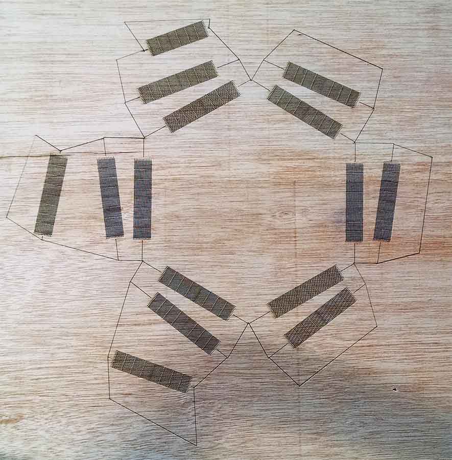
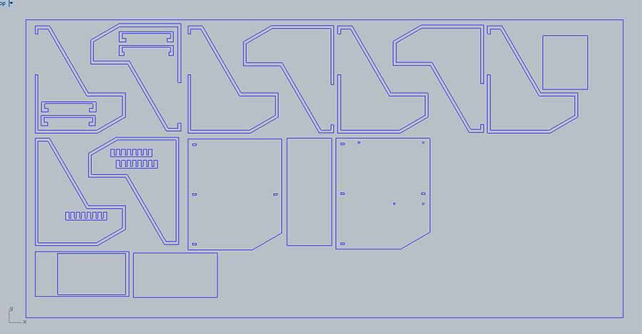
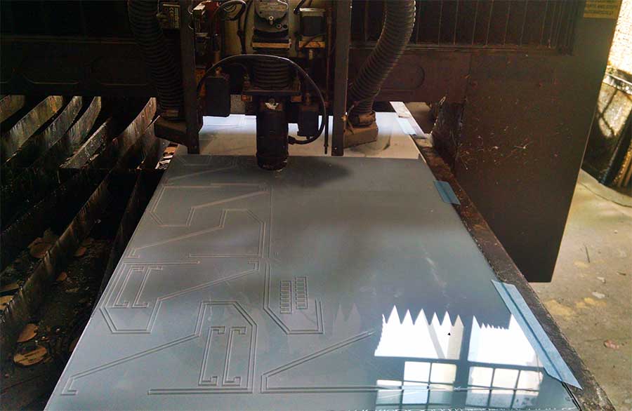
_LASER CUT
Before laser cutting the pieces in acrylic, I did several material tests as my initial idea was that the system was part of a pot. Neither the materials of the design worked so I started re designing with another concept.

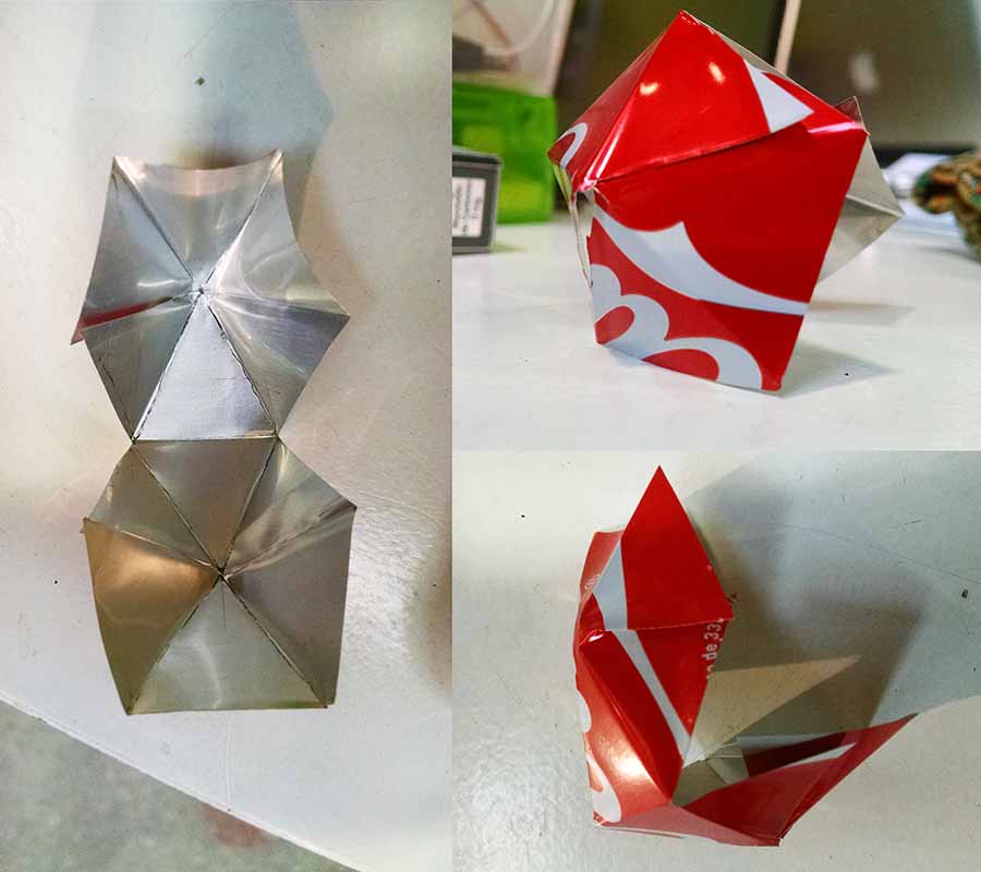
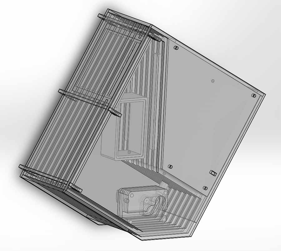
In the end, as I separated functionalities I thought doing it in acrylic was a good idea, to make it only as a shell, protecting everything that happens inside.
Designing in Solidworks taught me that you can save a lot of material, as you haver very little margin of error. So as soon as I had the design ready it was cut in 3mm methacrylate in two different times.
First time: SPEED 20 - POWER 90w
Second time: SPEED 60 - POWER 120
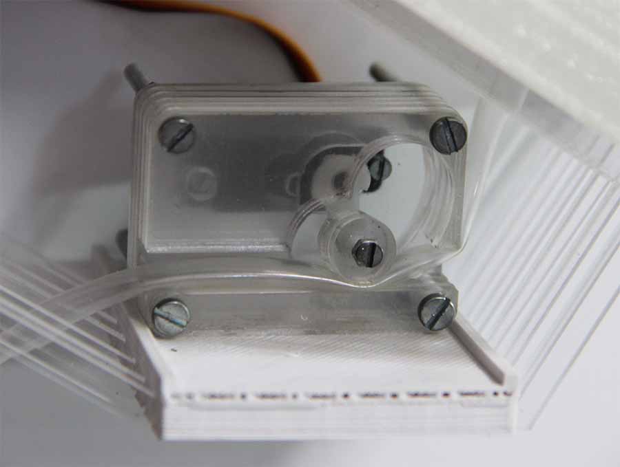
Finally, for the water pump I used the same procedure. I used a 3mm acrylic laser-cut pinche valve, stacked and held together with machine screws. Originally it is designed for a 6 mm silicon tube but as Im using solar energy to make the servo move, and after testing a lor of different tubes you can use 7mm black cable tube or 6mm plastic very flexible tube.
What I have also changed from the original design is the order of the layers to construct the valve. I have removed the second layer and instead added two n3 layers, to be able to fix the acrylic wheels to the servo arm with a nut and it needs space to move.
 Acrylic kit .dxf
Water pump .dxf
Acrylic kit .dxf
Water pump .dxf
_PROGRAMMING
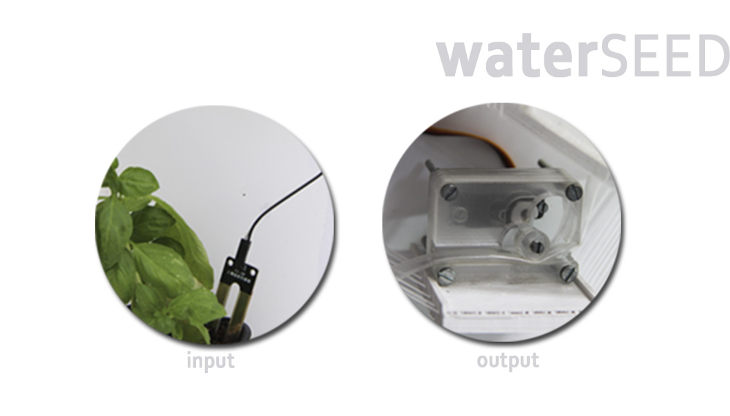
The programming was done with Arduino IDE, it involves monitoring and setting values between 0 and 1023 for humidity sensed through the serial monitor, a certain amount of time the water pump will remain open in milliseconds and the angle of the servo, in the case of this wate pump is 90 degrees.
If a certain value of humidity is sensed, the code will run moving the servo until the sensor gets humid again, looping constantly.
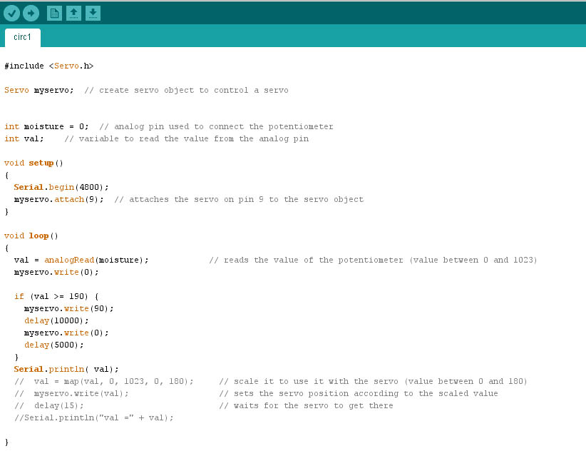 Arduino Code
_FINAL PROTOTYPE