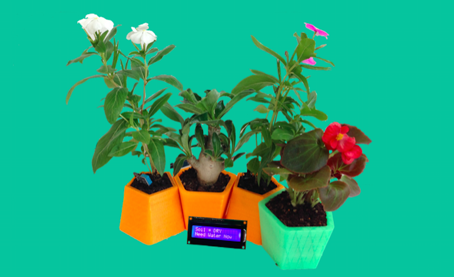
After thought a lot to the last step of the Fab Academy and thinking of projects very different and very complex, I finally focused on the usefulness of a final project for me, something that was in line with my interests and it was challenging to achieve but at the same time simple and functional. The final project was born, then, from the passion for plants and the need to manage some bonsai I have at home which unfortunately I can not devote much time. The right opportunity is the Fab Academy who gave me many skills and knowledge of digital fabrication and I completely beginner in each technique, I have tried to carry out a project simple and functional, and that would make me proud of what I did.
The idea of the project was shared with my colleague Youssef Bouali but it is the only step that we thought together. The rest of the project was developed ENTIRELY by me, by producing MOPOS following the suggestions of Neil and the rules of the final project.
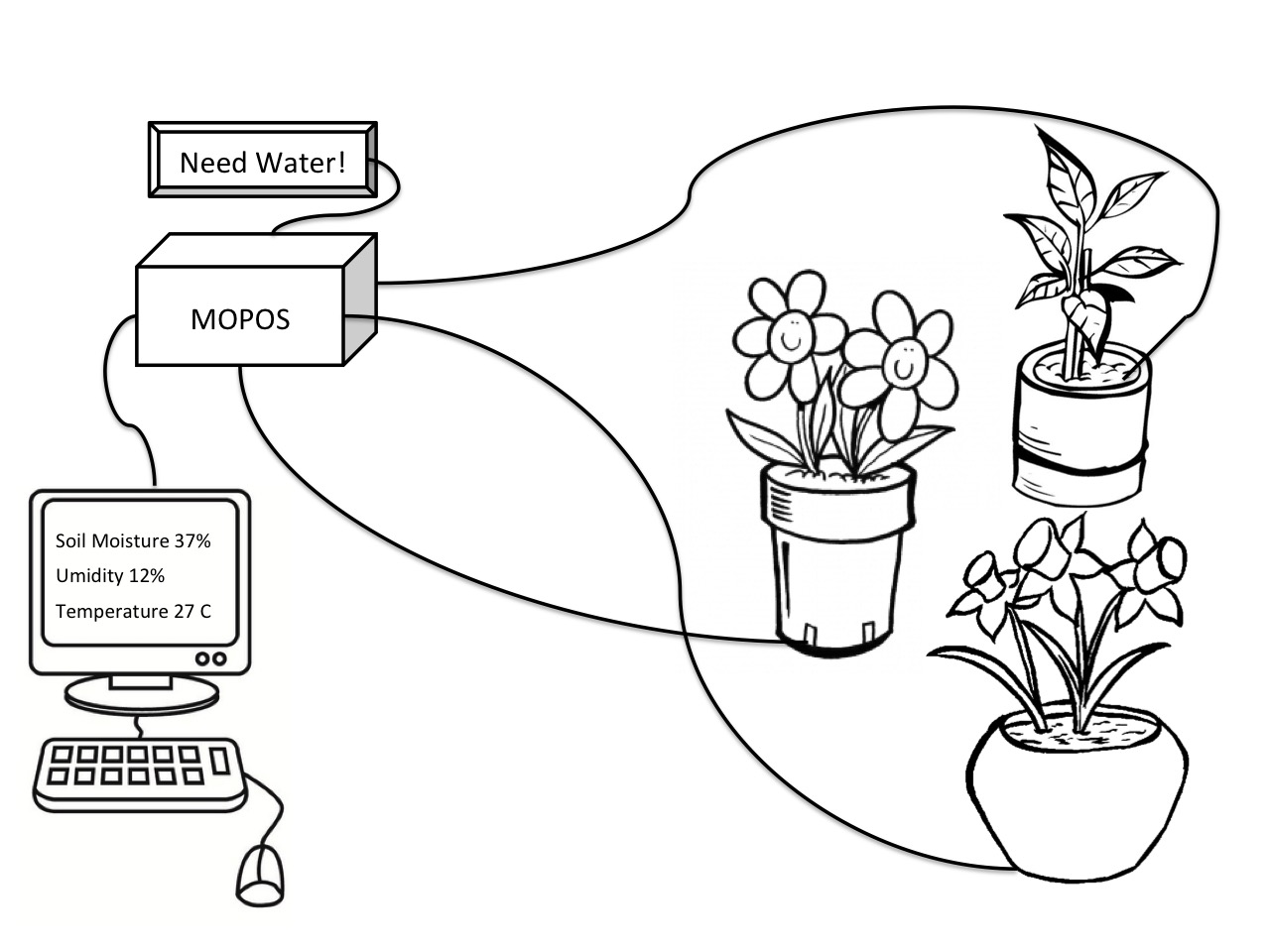
The project consists of a system of modular pots designed by me, that is connected a system controlled by an electronic board of my design and fabrication that controls three main sensors:
The board has been programmed to detect the sensor data, display them via an external display and process them to pack a single parameter that indicates when the plant needs water. To this is added an application, an interface in C ++, that can show the final results (which in the future , and with more time I would also add a web app), and a housing for the board made of silicone rubber obtained in a "craft" way through a cardboard box and a rubber tube.
On the following pages the process of realization of MOPOS will be explained in detail , and will be provided all the files needed for its replication
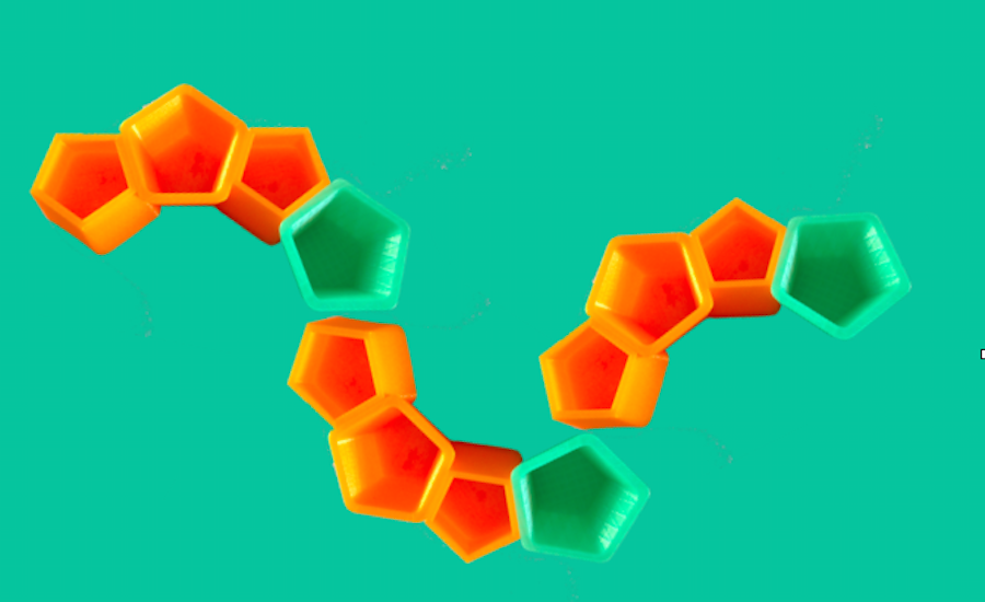
The idea has always been to create modular objects, especially as it comes to produce pots for domestic use. Looking on the web I saw many other projects with modular pots but did not like the idea to fit together the pieces and make them modular but always rigid format. I liked the idea of pots to keep at home, beautiful to look at and usable and adaptable as needed. So I started working on Rhino a polygonal shape that featured two different figures that were united with each other.
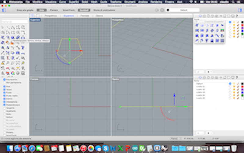
Then I extruded surface along a tapered curve to give an angle that would allow me to have an object from the bottom closer than the top. After extruded I made a hole in the object with the distances that I had decided through a boulean difference with an object 20% smaller. So I got the first form of my pot.
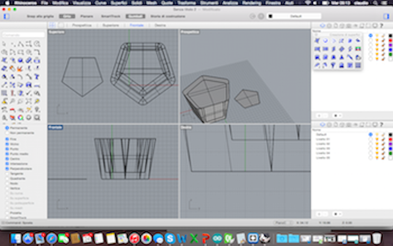
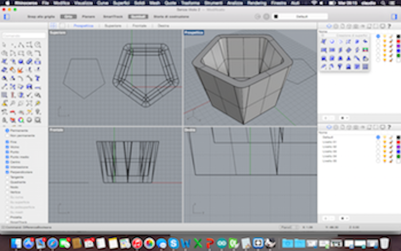
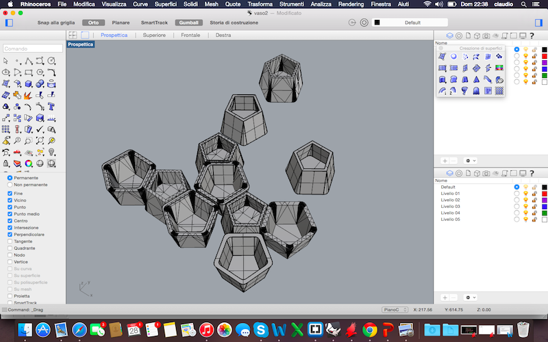
To achieve the second type I started from the first object but solid and filled and I flipped it, I then created a new object of 20% smaller and with the difference boulean I just created the second geometry. I obtained two types of pots, with simple design but nice and be moved towards in several positions and especially replicable and adaptable to the desired quantity. The pots are now ready to be printed!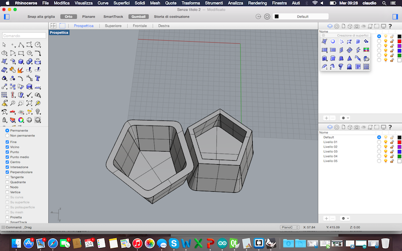
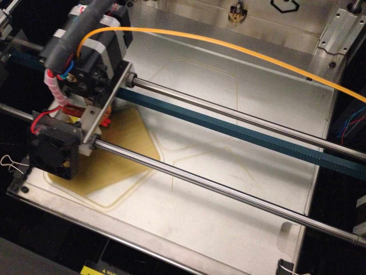
I printed the pots with PLA of 1.75mm initially with a Sharebot NG 1EX. Then there were some problems with a failed fan, and so I continued printing the other pots with a Prusa i3 Hephestoes. To create the GCode, I used CURA, changing according to my needs time settings infill. The following are pictures of CURA and the first stages of printing on Sharebot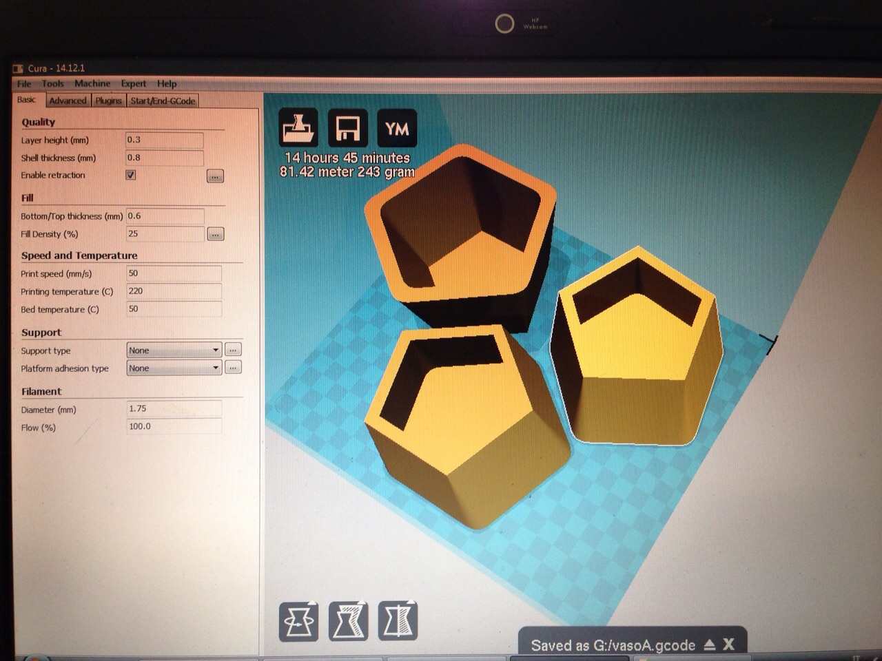
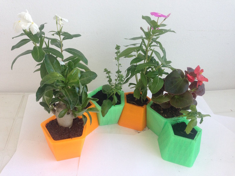
 After about 4 hours for each pots, this is the final and satisfactory result:
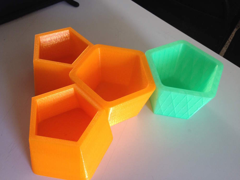
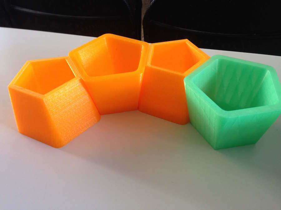
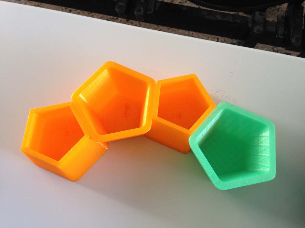
3D files of pots are available for download here:
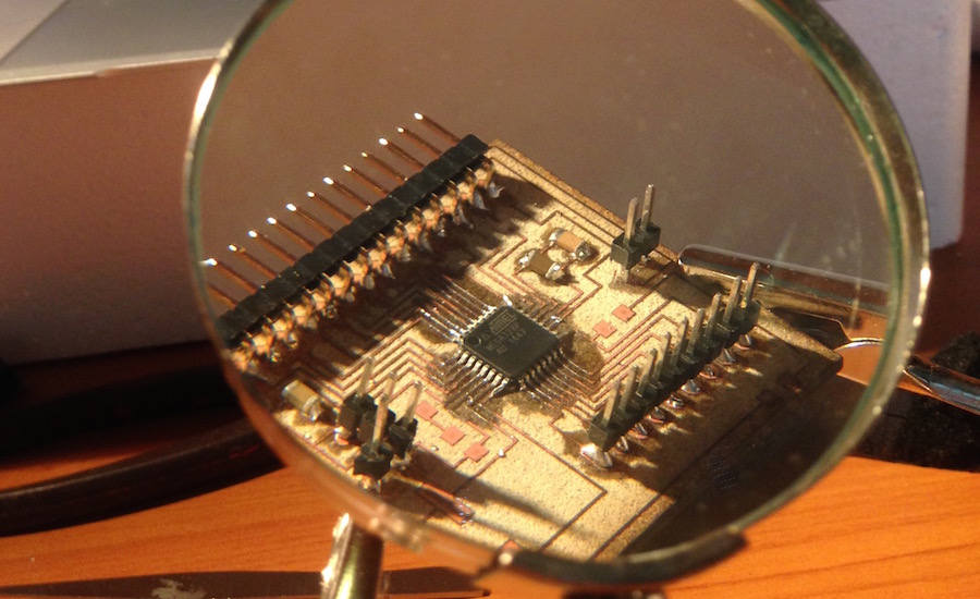
The Board of Mopos is a customization of a microcontroller manufacturable within any Fab Lab. The starting point for producing my board was in fact the Satshakit conceived by my colleague Daniele Ingrassia. I initially used the original board for my final project, but then after the suggestion of Neil during the presentation of the project, I modified the Satshakit according to project requirements.
Starting from this type of microcontroller with Eagle I modified the design by adding pins for the various input sensors and for the display of the output for use with Mopos. These are, firt the starting Satshakit and then the details of the changes: 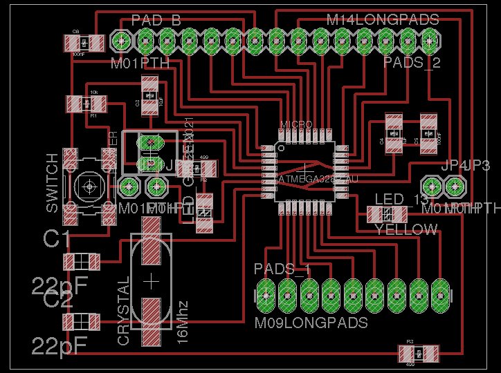
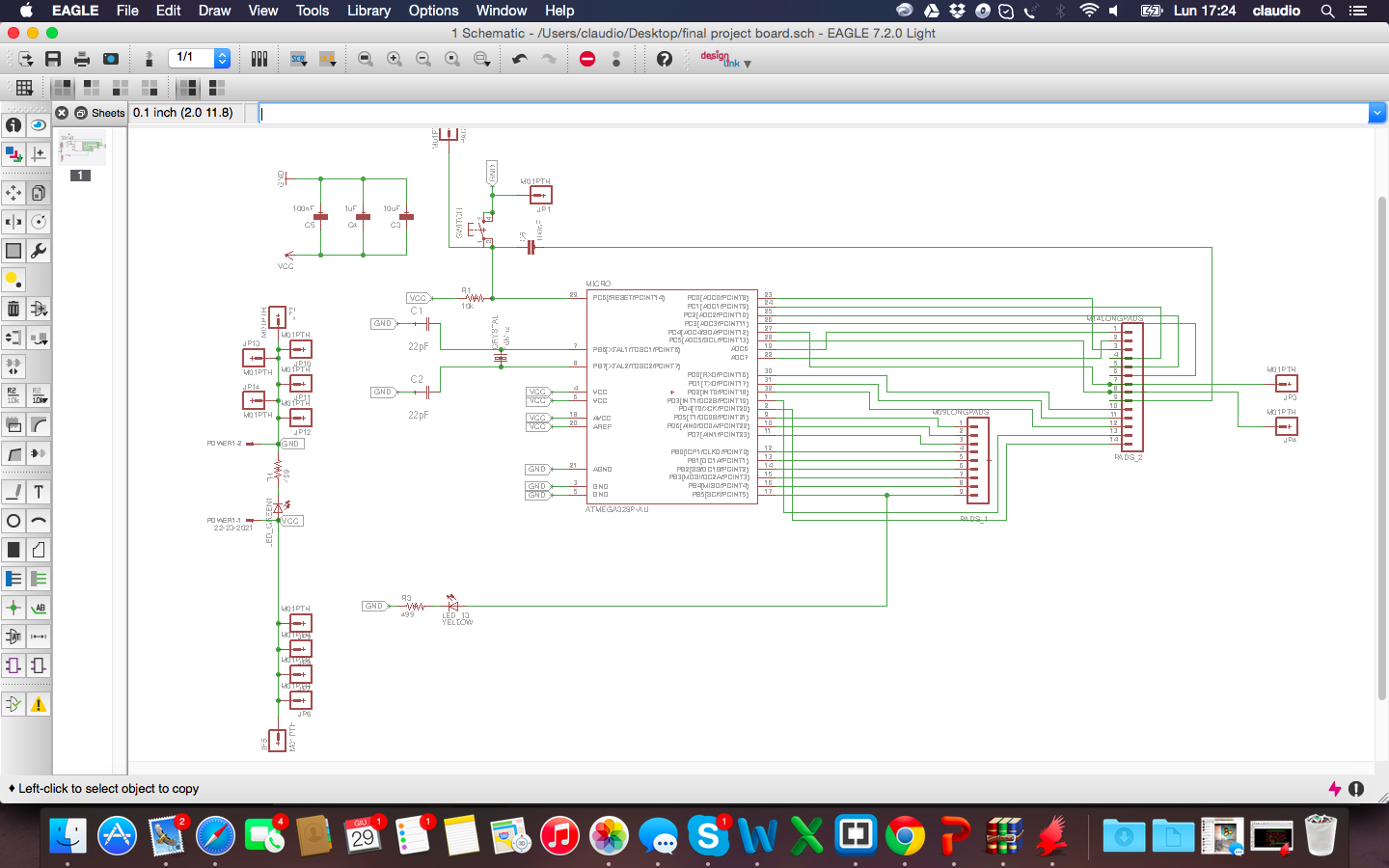
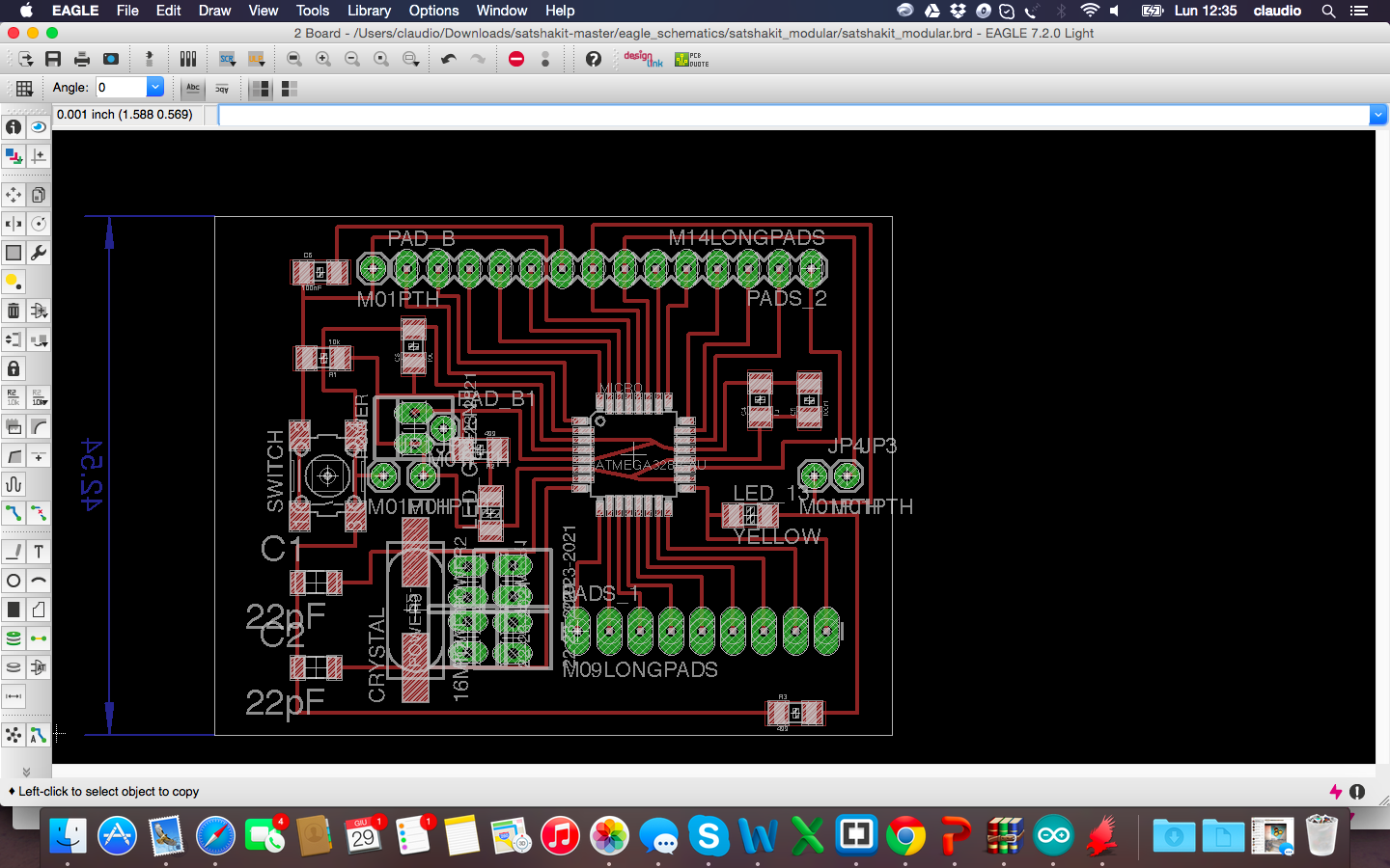
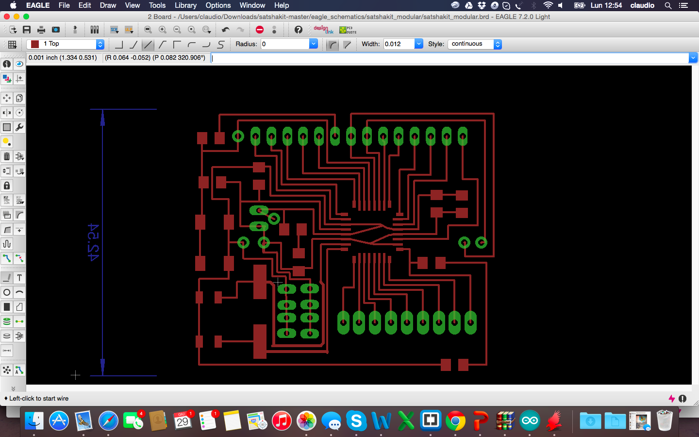
And these are the details of the pins: 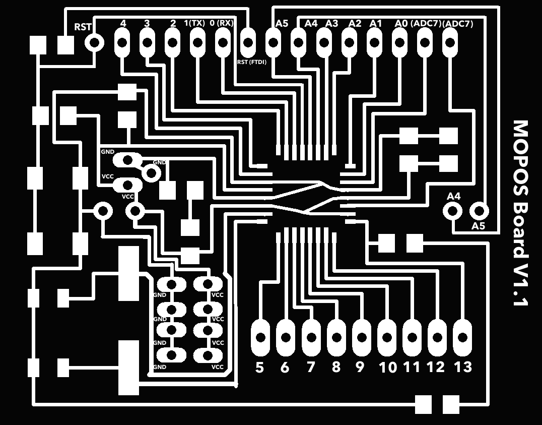
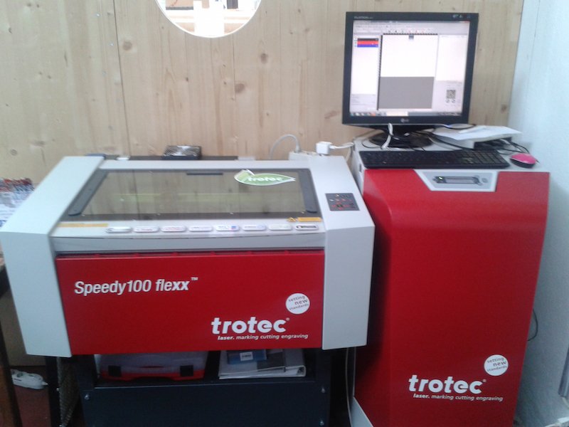
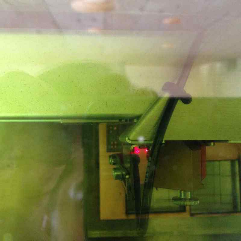
Formaking the board I used a Trotec Speedy 400 flexx to engrave the board, this machine has both CO2 and fiber laser technologies: 60 watt CO2 laser, 30 watt fiber laser. Here you can find the description of the process and experiments done in the lab on machinery.
These are some pictures of the making and soldering phases
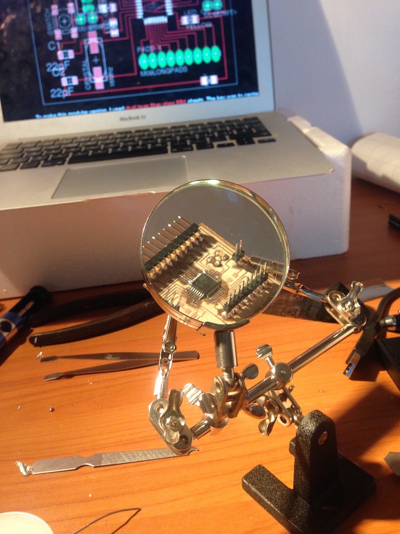
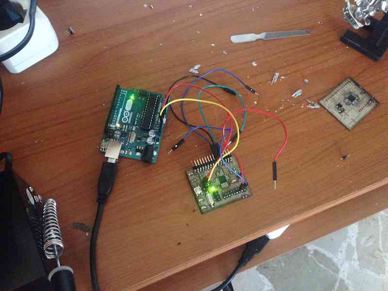
After finished soldering, i followed the instruction published of Satshakit page for load the bootloader with Arduino IDE and starting to programming the board
Files Eagle are available for download here:
Once assembled the board with all the parts specified, I wrote the sketch for the final project. I have integrated the functionality of the various sensors, first detecting the individual data and then crossing them to obtain a parameter of Threshold. The sensors to be used are:
The last two sensors are assembled in one sensor: DHT11
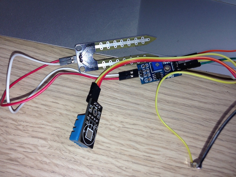
Measure the individual sensor data was relatively simple, so for a first check I printed it on the serial monitor of the Arduino IDE after connect sensors to my board as below:
This video shows the results:
Final Project programming board sensors from Claudio Pecere on Vimeo.
The next step was to also connect the other two elements of the final project:
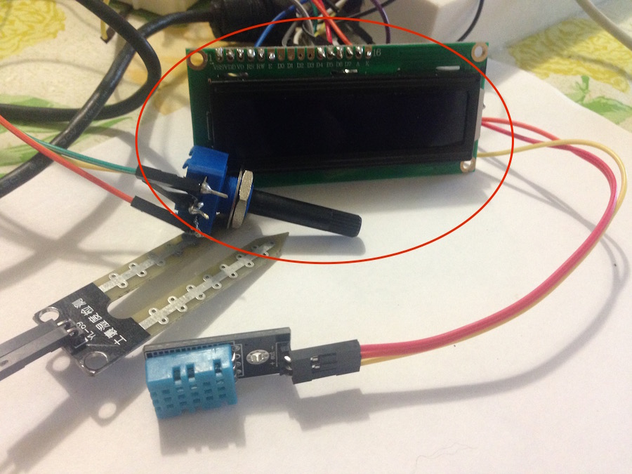
This is how to connect to an Arduino and easily to my board
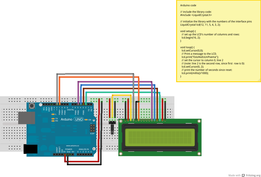
I tried also a simple sketch, an hello world just to understand if it works
Final Project Output device Test from Claudio Pecere on Vimeo.
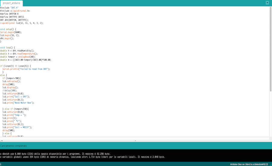
Now I'm ready to write the final sketch. The code should allow to receive data from the sensors, print them on LCD and process parameter "Need Water" or "soil still wet" according to the data of the soil. The display will blink the message in case of need of water. Below the connection between sensors and my board:
This is the final sketch and video related
Testing Final Sketch from Claudio Pecere on Vimeo.
The final Sketch is available for download here:
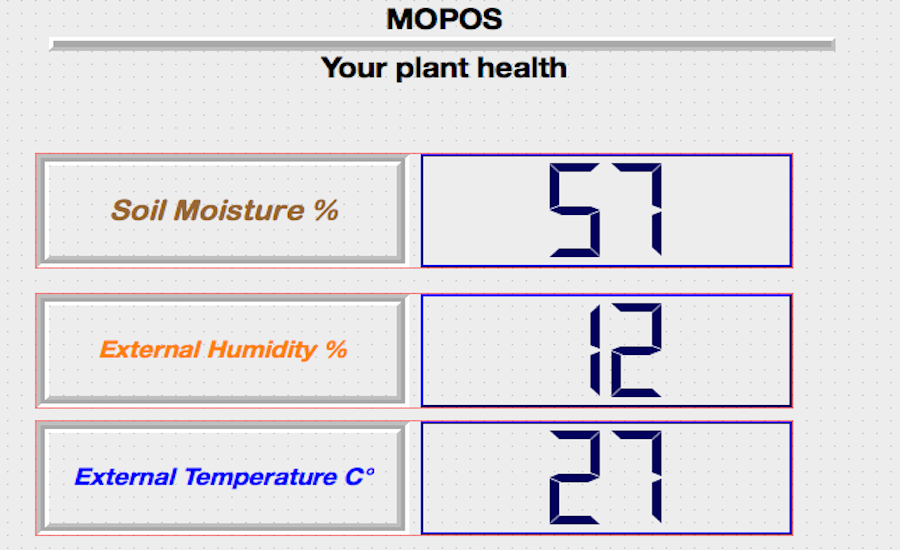
In addition to printing the results of the sensors on the display I tried to design an interface in C ++ through the use of QT that I had used even in the exercise of week 14. Again I had many problems with the serial ports of Arduino and once again the solution was to use a Windows PC because the Mac did not recognize the correct serial ports. I then set the graphics in a way not so amazing since QT offers features rather basic and 80s. The interface at this stage of my final project is useful to check the results without having to use the IDE. In general, however, the functionality of the project is enough the display but the interface will surely be useful in the future when I will send the data to a web app to view them remotely. 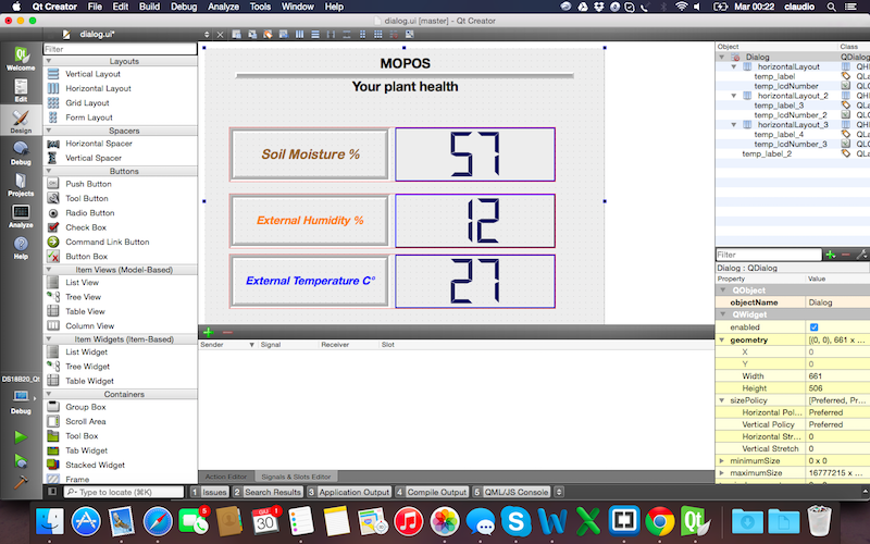 This interface code of QT
This video shows the testing of the interface
Testing Application Interface from Claudio Pecere on Vimeo.
All the files related to the application interface are avaible here
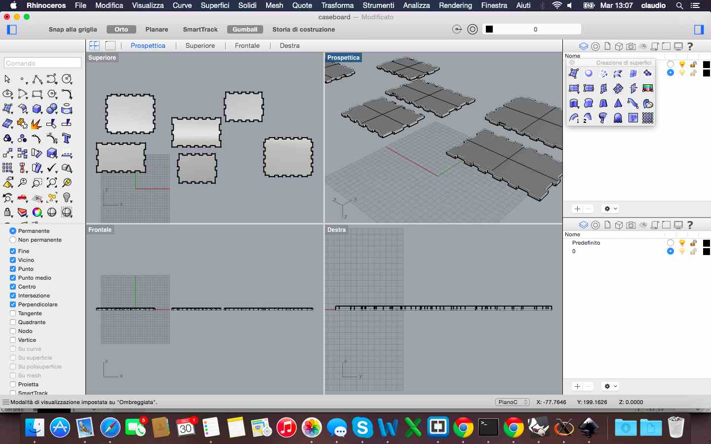
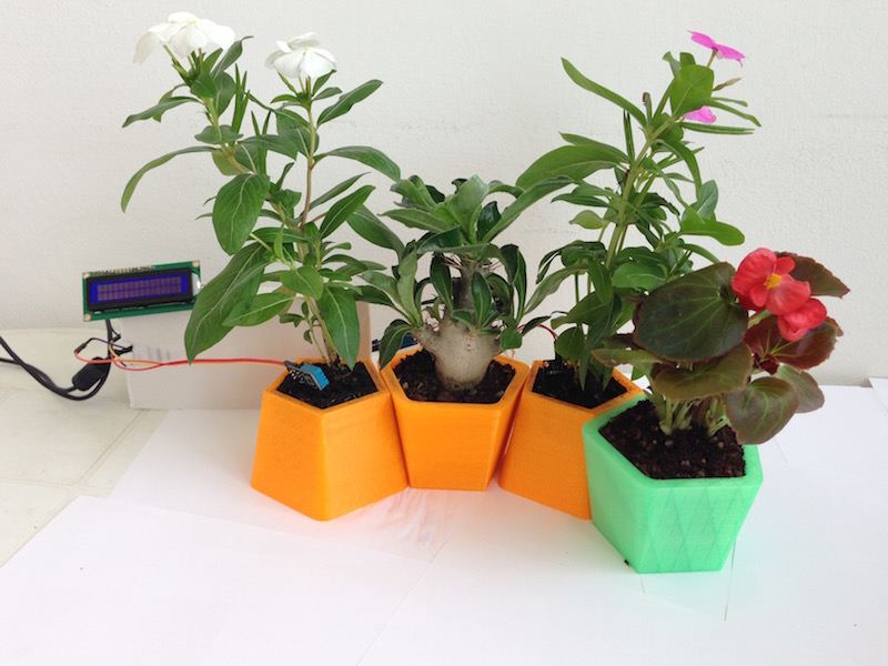
The last phase concerns the assembly and testing of the final project. Fortunately, it works fine, although I hope to make the improvements planned in the concept stage in a few months after the end of the Fab Academy. The board, vessels, sensors and interface are now assembled.The last point that I wanted to take care of is a case for the board and annoying wires. I also designed the box but unfortunately not being at the lab in the last days, I could not cut. 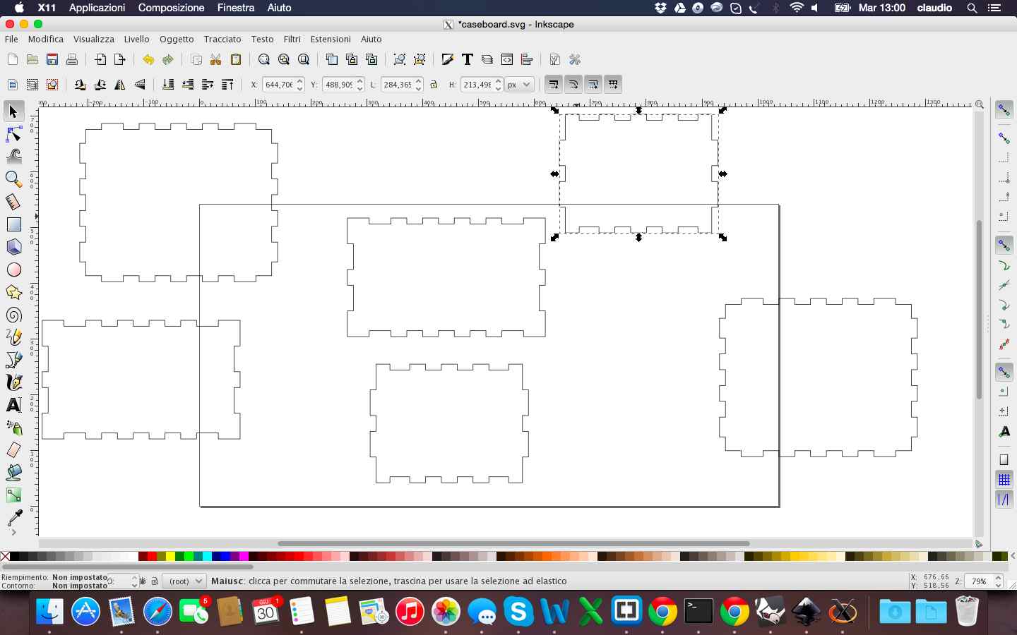
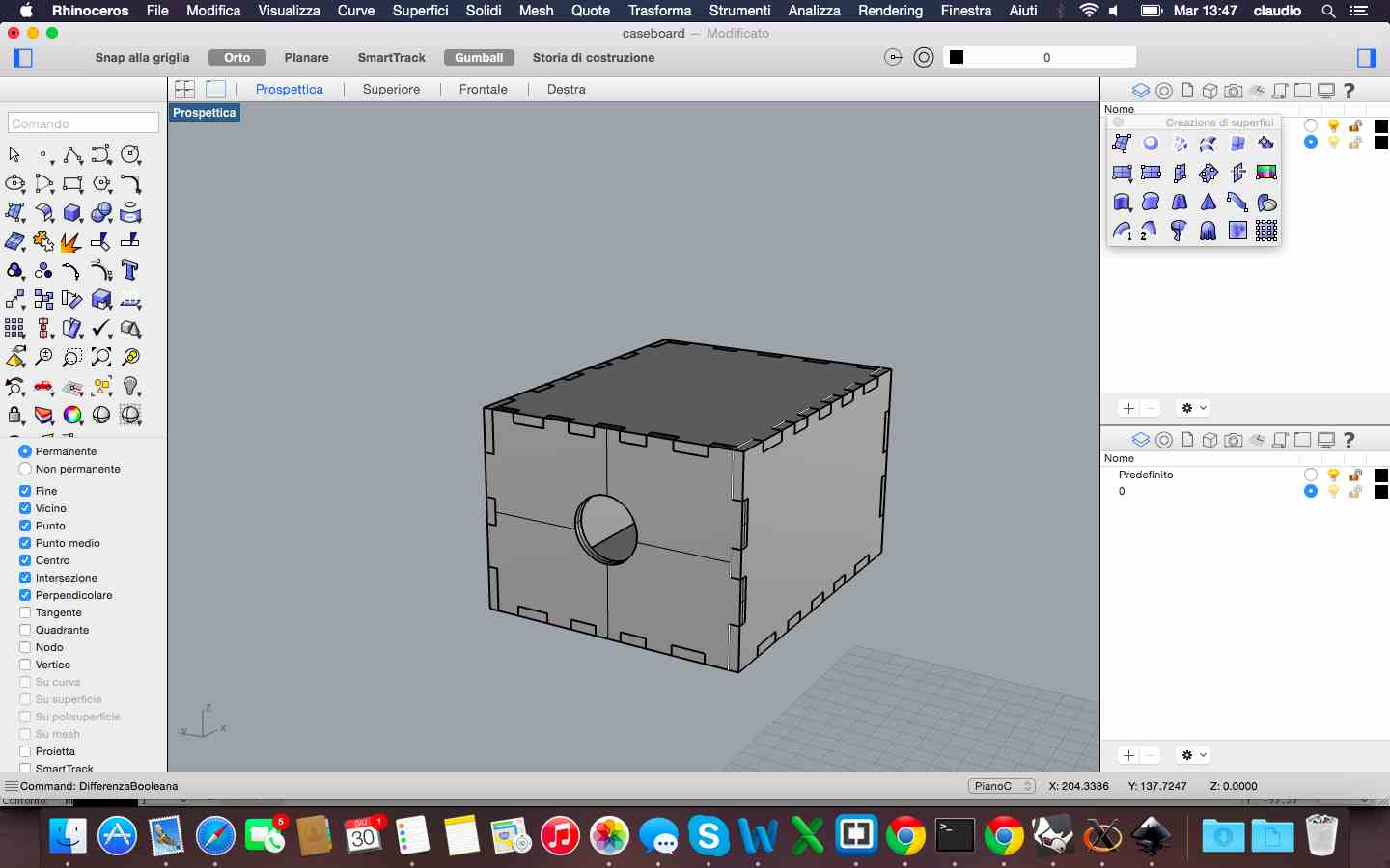
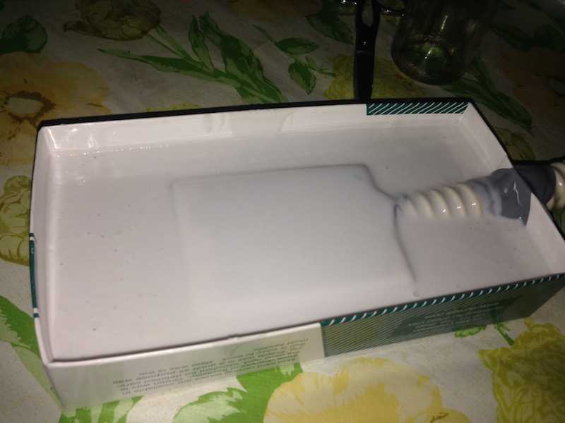
So I handcrafted a case made with silicone rubber for molds and a box of the right size. At the end it came out a result not just in line with the principles of digital fabrication but certainly useful to hide the wires at the sight of my nieces! 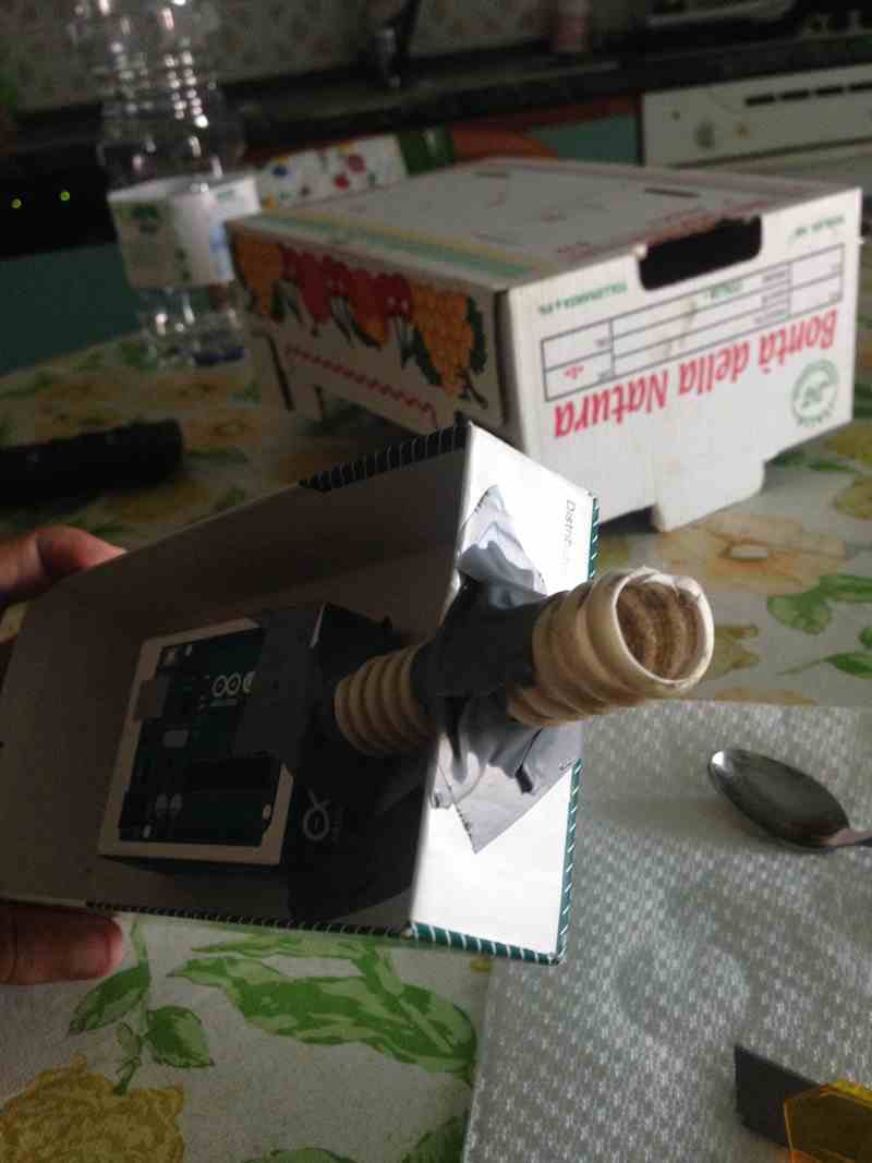
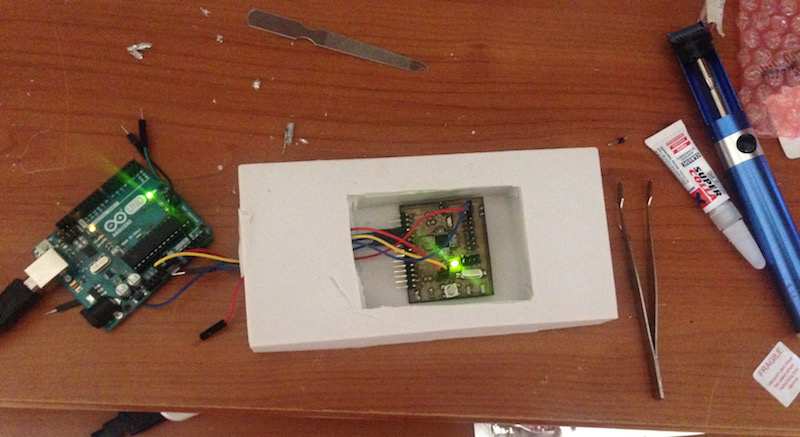
These are some pictures of the assembled final project and the video of the final test. 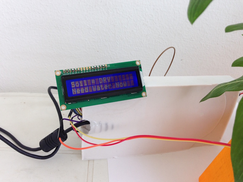
Final Project Demo from Claudio Pecere on Vimeo.
Finally this is the BOM of the project
The file of the box not cutted is available for download here:

