Applications and Implications
The choice of the final project it was not easy. It's a great responsability if:
- You want to make an usefull device
- That covers a need or lack
- You need (or want) to practice almost all the Digital Fabrication areas
- You have to make everything, yes everything, all circuits, all devices, all all! (to learn and practice as much as you can)
One of the most imporant things is being realistic and know your capabilities. Making mistakes of course, since it is fundamental to learn, but not to fail just for trying to overcome your capabilities and limits.But often you do not realize this until it comes time to do the full development of the project, near the end of the Academy.
Brainstormings, many many brainstormings. Besides to search for a usefull project, I was thinking of building something related to my hobbies, Space and Astronomy. Finally, I select a prothesis prototype project.
The Device: What is it? What it does?
The Hand Exerciser is a device to help people with degenerative diseases in their hands, such as osteoarthritis or arthritis, to perform the necesary exercises that improve and maintain their mobility, strengthening muscles and tendons. This device is particularly suitable for people who have lost considerable mobility. Mobility not only prevents stiffness, but the loss of muscle mass, which further worsens the condition.
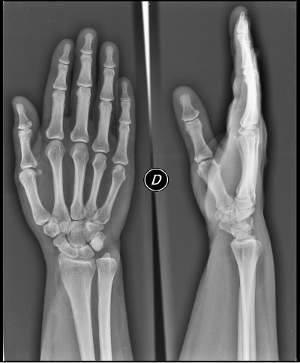
Mile's X-ray hand, during a medical check. I'm still on time to avoid stiffness doing excercise, but there are a lot of people, specially adult people, who lost mobility for not doing exercises routinely.
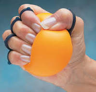
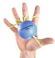
The most commong exercises to keep hands mobility is to press a small rubber ball, opening and closing the hand. Now we can found balls with rubbers to adjust to the fingers.
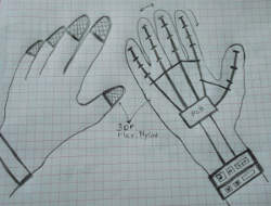
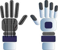
At left, the first sketch. At right, the first design made in Inkscape.
Something similiar already developed?
Most projects involving hands are prostheses for people who either have lost some phalanges, some fingers or the entire hand. This device is not exactly a prothesis, is a device to exercise the finger joints. Is like a glove that persons adjust in their hands. We can find some excerciser devices for people with such diseases, but are manually, they don't have any electronic device to help people, specially adult people who has lost mobility, to do the excercises. This Fab Lab device is automatic, you just need to switch on and select the routine you want to perform.

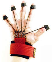
On the market you can find some simple devices to do hand exercices, like Xtensor and Manus, but they are manually. If you lost mobility or some adult people do not have enough strength to do the exercises with these devices, do not improve.
Materials and components, where will they come from and cost
Originally, since the concept phase of the project I was working with the idea of using 5 mini servo motors to blend the fingers of the device. Even with the output device assignment I use a mini servo thinking about that. But I really didn't know the limits of the mini servos power, is not enough to move a finger. Maybe I can find some mini servos with enough power but to expensives. So instead to use five mini servos, one for each finger, I have to use just one big servo to move all the fingers. Even if I know that with a unique uniform movment of all fingers is usefull (like you made when you use an excersice ball), I'm not really happy with this. I can use five big servomotors, but I don't want to put a big device on the arm, specially for the adult people. The device must be confortable and easy to adjust. So I will try with five and if the result control system box is to big, I will use just one servo.
Even I thoutgh to use some special materials like Flexinol or Nitinol, to return the fingers to the original position, but also they are not strong enough to do that. So de firts idea, alway thinking in a confortable device, was to avoid the use of springs, and I thought to use flexible cord. But with this solution I had to think to put the servo wires in one side, and the flexible cord on the other side, and this does not convinced me. So thinking about one unique system to blend the fingers and return them to their original position, I decide to make test with push/pull cable, to adjust just in one side of the device.
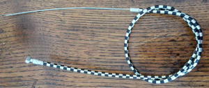
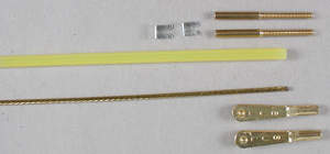
At left, the push/pull bicycle brake cable that I am using on the test. At right, a push rod cable, used on a RC models I will use once I have the 3D printed part.
Even if I know that I still have to make some test, I make a firts version of the list of expected materials and components, and the estimated price, planned to produce the prototype. But surely there will be changes after the first tests were done. All materials can be found in the Fab Lab, except the push/pull cable. I buy one of a bike break just to make some test, then, if it works, I am going to serach for a finest cable, because I am sure is going to work better with the servos, than the first I use which it is very thick.

Parts and Systems processes
Except for the servomotors, all the parts of the device will be made by myself. I'm designing the "hand" in Solid Works to 3D print it. For the PCB I will design the circuit in Eagle, milling it and solder all the components. For the control system box, I will design it on Solid Works and made it with transparent acrilyc, cutting with the laser machine. Finally, I have to program the system, using for example Processing language.
Tasks need to be completed
The task to be completed are:
- Design all the parts ("hand", PCB, system box) with Solid Work and Eagle
- Make all the components with the different processes: 3D printing, milling, soldering, laser cutting
- Program all the system
- Do the tests
- Do the corrections if needed
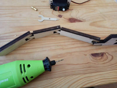
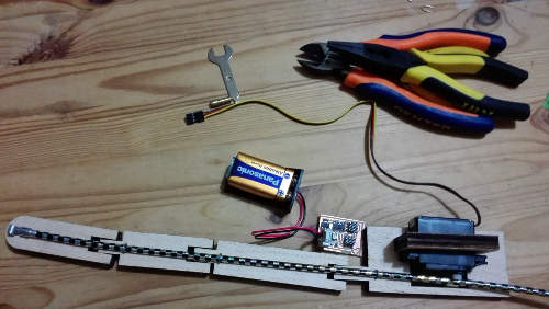
Assembling a "finger" to test the power of the servo motor and the system to bend it.
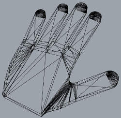
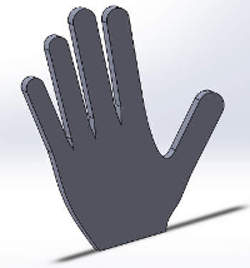
The first steps on the 3D design. At left, first attempts with Rhino 5; at right, the first lines made with Solid Works.
Questions to be answered
- The "hand" part, printed with flexible nylon will be enough resistant
- The push/pull cable is going to work blending the fingers and turn it to the original position, or I will need to use instead PCV wire and flexible cord finally?
- Servo motors with how much power I will use?
- Maybe if I use PVC wire and flexible cord I can use smaller servos?
Schedule
- 3D design: 3 days
- 3D printing: 5 hours
- Electronic production: 2 days
- Programming: 2 days
- Assembly: 1 day
- Test: 1 day
- Corrections: 2 days
How the project will be evaluated
The final project can be evaluated on the basis of the results and function of the prototype; by the research and test that I made in the assignments in which I could apply something to the project (3D printing and scanning, molding and casting, etc.); for the number of skills learned on the assignments that I will apply to the final project, such as:
- Computer-aided design
- Computer-controlled cutting (laser cutting)
- Electronics production
- 3D printing
- Electronics design
- Embedded Programming
- Input/output devices


