Networking and Communications
A new encounter with the electronics and programming. This time the subject is on networking and communications, and the assigmnent was, design and build a serial or wireless network connecting at least two processors.
My original idea was to make a laser communication system, but unfortunately I didn't find enough information about. Also this week we had a holiday in which we could not attend the lab, and had a lot of work with my professional projects.
I was interested on laser communications, since we're studying about the transmission of big data with laser beams between satellites in different orbits. So is a pending task, since it's an interesting exercise to learn more about laser transmission. So while the laser beam day comes, I did the typical wire communications systems. Nothing too exciting, but a good entry into the world of communications and networking.
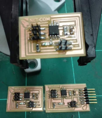
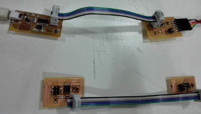
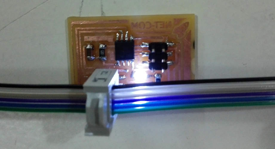
For our comm system we need a bridge and two nodes. The first step was to design de circuits, as usual with Eagle (Eagle bridge and node schematics and boards files. The next step was to mill the PCB's with the Roland Modela milling machine (bridge and node traces and outlines png files), and finally, sold all the components.

This is the BOM for our PCBs:
Bridge
- ATTiny45
- 1K Resistor
- 10K Resistor
- 1uF Capacitor
- LED
- FTDI header
- 2x3 STM Header (ISP)
- PinHD-2x2-SMD
Nodes (x2 in my case)
- ATTiny45
- 1K Resistor
- 10K Resistor
- 1uF Capacitor
- LED
- 2x3 STM Header (ISP)
- PinHD-2x2-SMD
Finally you just need a piece of FTDI cable and three conectors to make the system.
The next step was to programm the three microprocessor (you can download the Neil's C files). As usual, I can't program with C my PCB's due to the Windows 8 OS, so I need to ask for some help. You just need to assign each PCB with a different number, as an ID, on the command line #define node_id '0' .

Finally, send some commands lines, for example to make blink the Leds, with Arduino IDE, to check the correct operation of the network.


