Electronics Production
This weeks class of Fab Academy 2015 was about the creation of PCB’s and their direct cousins (any form of circuit medium). This week is a skill oriented one and made to verify our capabilites for future lessons.
To quote Prof Neil Gershenfeld:
The last thing you need to do is wash it. Finger prints will etch the board not in a day or two, but in a month or two.
I hope my board still works in a month or two.
My plan:
- Day 1 - Millliing
- Day 2 - Soldering
- Day 3 - Firmware
You can find all my source files here: Electronics Production.
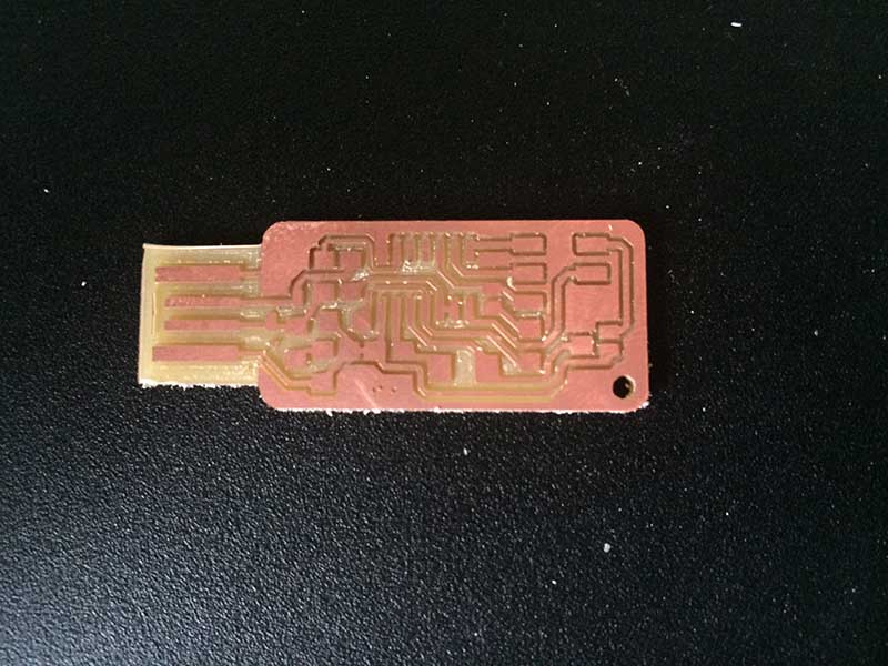
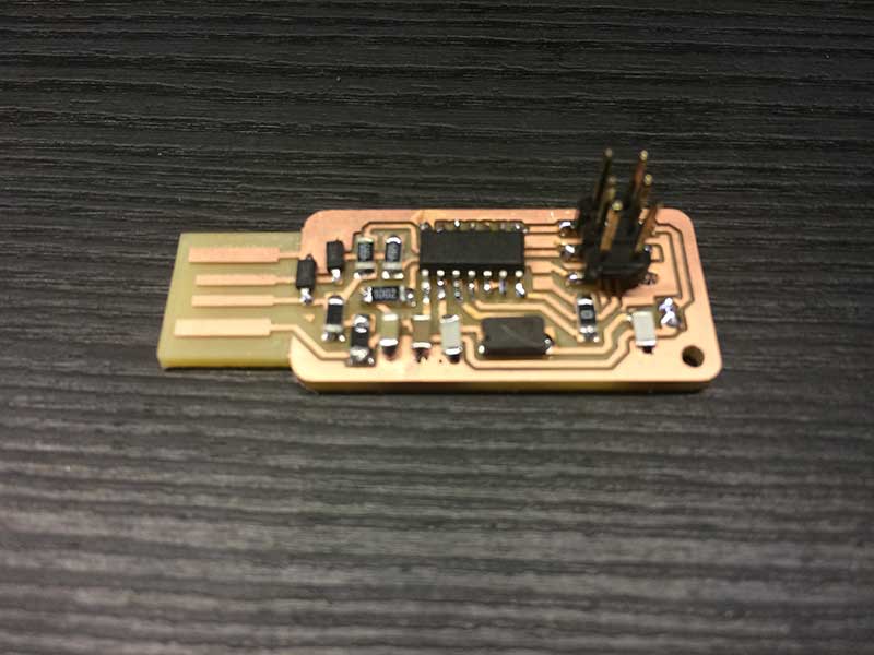
We chose to follow the Andy’s Fab ISP Key to make a simple usb connection that only requires a small amount of material to be added to the back (in hind site I would add the backing before milling next time since it is an additional sacrificial layer.)
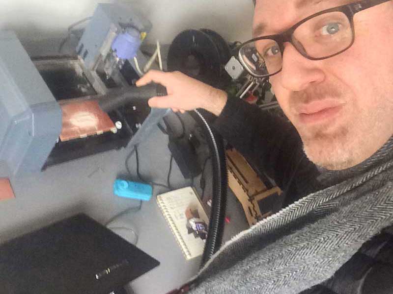
Millling
We have three mills at Fab Lab Cascina, a Modella, an iModela and a SRM–20. I went with the iModela as it was available. My first attempt failed as I was using my own MacBook OSX 10.10 and although Fab Modules installed the Serial module is not connecting. I only have Windows virtualized at this point so I switched over to the Lab Milling Unix laptop. The web based Fab Modules worked while we were aligning and preparing, but we had to reload the design files and it caused a problem in the web server. Instead of rebooting we loaded the older desktop version of Fab Modules. I added my own logo to the Andy version of the FabISP. Unfortunately my logo was so small that the Mill could not mill it and I ended up with three holes. It was a good lesson in what size detail is needed for fab modules to interpret something correctly. It seems to be about 1mm square.
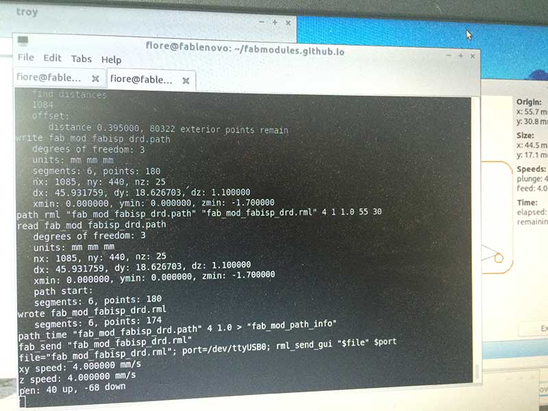
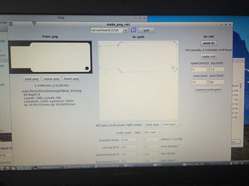
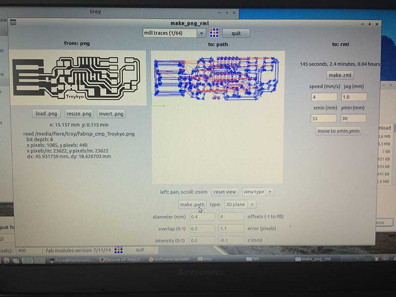
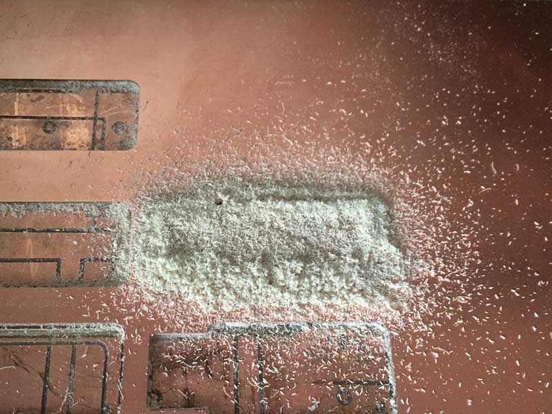
The 1/64 milling went well once things were set up. It took me a few tries to get the bit in correctly, but once there it was easy to understand. Fiore walked me thru it. After that the 1/32 milling was a cake walk. It was interesting to see the left over shards and scraps that needed to be blown away to avoid a short circuit.
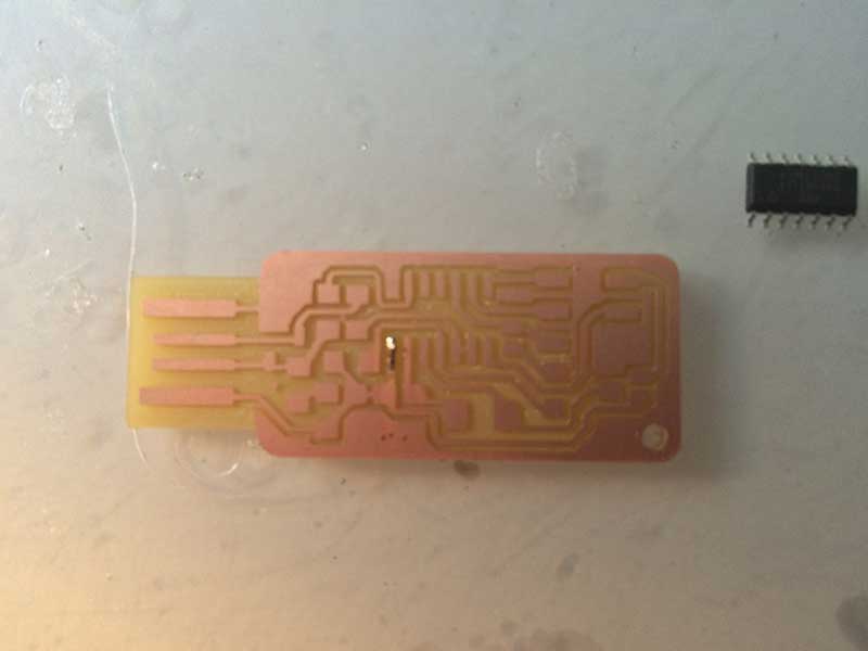
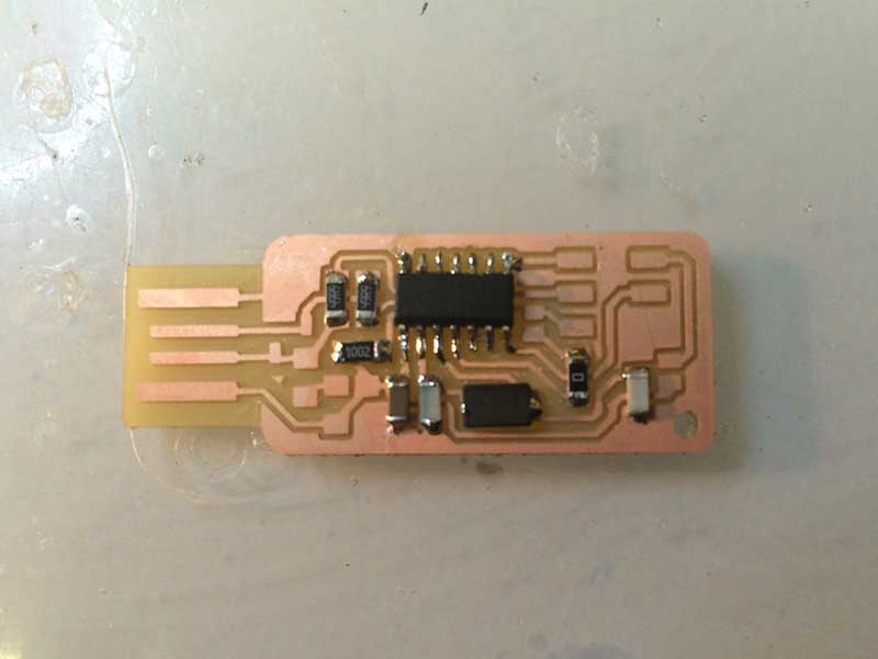
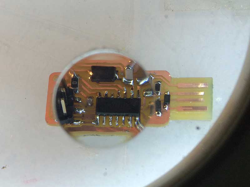
Stuffing via SMD Soldering
While I’ve sewn countless circuits and soldered quite a few thru hole boards, this is my first adventure into SMD soldering. I was sorting all of the components in the circuit diagram found on Andy’s Fab ISP key page. Fiore came by and gave me some good advice by pointing me to his [Bill of Materials] (http://fabacademy.org/archives/2014/students/basile.fiore/images/week04/fabisp_bom.jpg) from when he did Fab Academy. Fiore also taught Betty and I how to mount the attiny: first place it with the tweezers and then gently tap it into place. Next, apply pressure with the tweezers and solder the bottom left, then upper right. Then move clockwise being sure to count to three and apply the right amount of solder. It takes practice, but a good solder is not bulbous and remains shinny. Work out from the attiny to make sure that pads are not accidentally skipped.
Firmware
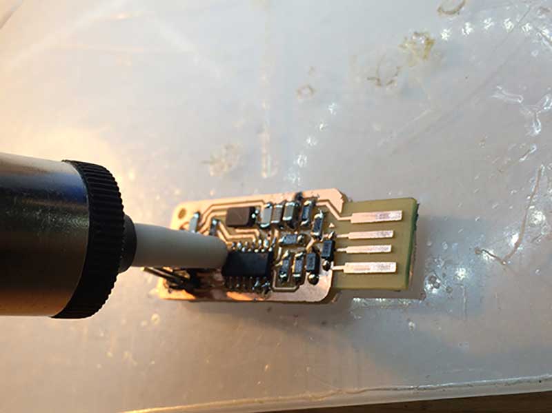
It was exciting to stuff the board, so I stayed at the Fab Lab Cascina late to upload the firmware. I downloaded CrossPack - A Development Environment for Atmel’s AVR Microcontrollers and set to loading the firmware. If you scroll down on Fiore Basile @ FabAcademy 2014 you’ll find a great fix to the makefile that has been set for avrisp’s, not the usbtiny. Although everything was right and Fiore confirmed it, my firmware would not load. But this was not the end of the world, no one elses' would either, so I gave up and went to sleep for the night.
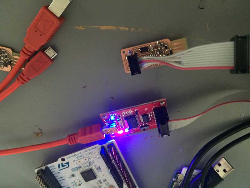
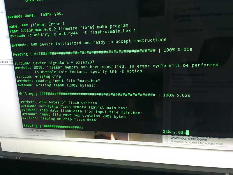
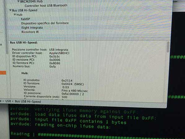
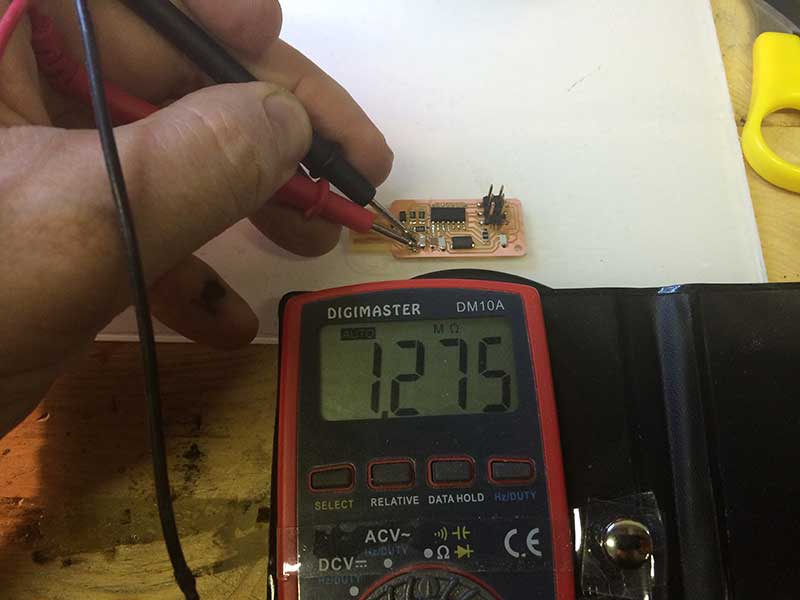
Thankfully the next day (Sunday) friend of the Fablab and Master Electronic Engineer Stefano Panichi came by and helped me trouble shoot. Usually it’s impossible to test a circuit once soldered because the values are compounded by the micro chip, but if you set your tester to diode mode magic happens. I documented the explanation in Italian here. With the tester in diode mode you can test to see if information is passing thru the microchip. We touched one lead of the sensor to ground and then tested all my pins. We found a short circuit to ground on the third pin we tried. Stefano pointed out that I soldered the wrong jumper as well. He also showed me which solders were done well and which were not (most were in the NOT category). It was really amazing to have a Master walk me thru the solders. (It turns out that everyone in the lab had at least one problem that was causing the board not to program.) With the soldering remade and the correct jumpers set the firmware uploaded with no problems. What would have been a complete fail was saved by the help of Stefano Panichi (@StefanoPanichi) | Twitter.
You can find all my source files here: Electronics Production.