David Montenegro
FAB ACADEMY 2015
Final Project | Assignments | Download | About | Contact
04_15 Output
On wednesday 04.08.2015 we’ve got the eleventh online lesson with Neil Gershenfeld.
The next lessons can be found on the Fab Academy account on Vimeo.
For this week the assignment was
** add an output device to a microcontroller board you’ve designed and program it to do something **
For this assignment I’ve made a 5x3 ledmatrix with a charlieplexing method.
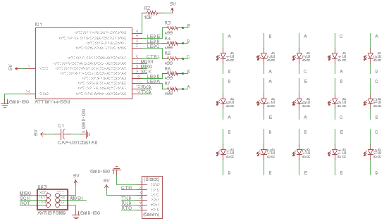
The board
To drive 15 led I’ve to use 5 pins: Here the pinmask
led0             led1             led2             led3             led4
pinA: OUT, Vcc   pinA: OUT, Gnd   pinA: OUT, Vcc   pinA: OUT, Gnd   pinA: OUT, Vcc
pinB: OUT, Gnd   pinB: OUT, Vcc   pinB: IN         pinB: IN         pinB: IN
pinC: IN         pinC: IN         pinC: OUT, Gnd   pinC: OUT, Vcc   pinC: IN
pinD: IN         pinD: IN         pinD: IN         pinD: IN         pinD: OUT, Gnd
pinE: IN         pinE: IN         pinE: IN         pinE: IN         pinE: IN

led5             led6             led7             led8             led9
pinA: OUT, Gnd   pinA: OUT, Vcc   pinA: OUT, Gnd   pinA: IN         pinA: IN
pinB: IN         pinB: IN         pinB: IN         pinB: OUT, Vcc   pinB: OUT, Gnd
pinC: IN         pinC: IN         pinC: IN         pinC: OUT, Gnd   pinC: OUT, Vcc
pinD: OUT, Vcc   pinD: IN         pinD: IN         pinD: IN         pinD: IN
pinE: IN         pinE: OUT, Gnd   pinE: OUT, Vcc   pinE: IN         pinE: IN

led10            led11            led12            led13            led14
pinA: IN         pinA: IT         pinA: IN         pinA: IN         pinA: IN
pinB: OUT, Vcc   pinB: OUT, Gnd   pinB: OUT, Vcc   pinB: OUT, Gnd   pinB: IN
pinC: IN         pinC: IN         pinC: IN         pinC: IN         pinC: OUT, Vcc
pinD: OUT, Gnd   pinD: OUT, Vcc   pinD: IN         pinD: IN         pinD: IN
pinE: IN         pinE: IN         pinE: OUT, Gnd   pinE: OUT, Vcc   pinE: OUT, Gnd
I designed the board with Eagle, but the routing was not straightforward, so the board looks a little bit a mess, but it works. I’d like to shrink the matrix board but in the upper right corner traces are too closer, so I’ll try for a different routing in the future to shrink it.
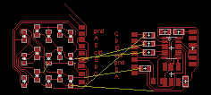
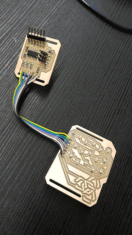
I made this with two boards because at the very begin I tried to make it wearable without any other part, that’s also the reason why I made two cut on the boards.
Pay attention at the directions of the LEDs and the correspondence between traces to connect the two boards.
As you can see there is also a drawing on the board; it should be some sort of button that close the loop using skin conductivity, but I’ve not implemented it in software. I’ve added it graphically, after exporting the board.
The code
Starting from the Neil code I made some customization.
First of all I’ve changed the pins for the pinout because I’ve used different pins.
Than ports and directions registers have been edited too.
Here the code to cicle and test all the leds.
#include <avr/io.h>
#include <util/delay.h>

#define output(directions,pin) (directions |= pin) // set port direction for output
#define input(directions,pin) (directions &= (~pin)) // set port direction for input
#define set(port,pin) (port |= pin) // set port pin
#define clear(port,pin) (port &= (~pin)) // clear port pin
#define pin_test(pins,pin) (pins & pin) // test for port pin
#define bit_test(byte,bit) (byte & (1 << bit)) // test for bit set

#define led_delay() _delay_ms(1) // LED delay

//#define led_port PORTA

//#define led_direction DDRA

//David's pinout
#define A 0 // led pin A
#define B 1 // led pin B
#define C 2 // led pin C
#define D 3 // led pin D
#define E 4 // led pin E
#define BUTTON (1 << PB7) // button pin

uint8_t ledPin(uint8_t ledNumber){
	if (ledNumber == A){
		return (1<< PA2);
	}

if (ledNumber == B){    return (1<< PA3);
}
if (ledNumber == C){    return (1<< PB0);
}
if (ledNumber == D){    return (1<< PB1);
}
if (ledNumber == E){    return (1<< PB2);
	}
}

volatile uint8_t* ledPort(uint8_t ledNumber){
	if (ledNumber == A || ledNumber == B) {
		return &PORTA;
	} else {
		return &PORTB;
	}
}

volatile uint8_t* ledDir(uint8_t ledNumber){
	if (ledNumber == A || ledNumber == B) {
		return &DDRA;
	} else {
		return &DDRB;
	}
}


void flash(uint8_t f, uint8_t t, uint8_t delay) {
	//
	// source from, sink to, flash
	//
	uint8_t from = ledPin(f);
	uint8_t to = ledPin(t);

	static uint8_t i;
	//set(ledPort(from),from);
	//clear(ledPort(to),to);

	*ledPort(from) |= from;
	*ledPort(to) &= (~to);

	*ledDir(from) |= from;
	*ledDir(to) |= to;

	for (i = 0; i < delay; ++i){
		led_delay();
		*ledDir(from)  &= (~from) ;
		*ledDir(to)  &= (~to) ;
		}
}

void led_cycle(uint8_t number, uint8_t delay) {
	//
	// cycle through LEDs
	//
	uint8_t i;
	for (i = 0; i < number; ++i) {
		flash(B,A,delay);
		flash(C,A,delay);
		flash(D,A,delay);
		flash(E,A,delay);
		flash(A,B,delay);
		flash(C,B,delay);
		flash(D,B,delay);
		flash(E,B,delay);
		flash(A,C,delay);
		flash(B,C,delay);
		flash(D,C,delay);
		flash(E,C,delay);
		flash(A,D,delay);
		flash(B,D,delay);
		flash(C,D,delay);
		flash(E,D,delay);
		flash(A,E,delay);
		flash(B,E,delay);
		flash(C,E,delay);
		flash(D,E,delay);
	}
}

int main(void) {
	//
	// set clock divider to /1
	//
	CLKPR = (1 << CLKPCE);
	CLKPR = (0 << CLKPS3) | (0 << CLKPS2) | (0 << CLKPS1) | (0 << CLKPS0);

	//
	// main loop
	//
while (1) {
  led_cycle(1,100);
  led_cycle(3,20);
  led_cycle(100,1);    }    return 0; }
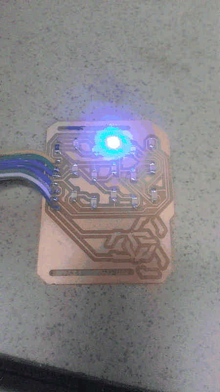
It presents a weird behaviour: after cycling the first 14 leds it should flash led 14, but it doesn’t; instead it flash the led3, led 6, led9 and led12 at low power
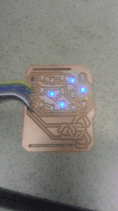
led3
	from	C
	to		A

led6
	from	A
	to		E

led9
	from	C
	to		B

led12
	from	B
	to		C
I tried also to verify the direction of the led14, but it’s ok. Right now I can’t explain this wire pattern.
Solved
It has been solved during the final project debugging.
The leds were arranged indexed not properly (just the last two) and so the micro sets to ground all the other 4 pins, to the tension was divided between leds. Fixing the array coordinates it works properly.