David Montenegro
FAB ACADEMY 2015
Final Project | Assignments | Download | About | Contact
03_11 Embedded Programming
On wednesday 03.11.2015 we’ve got the seventh online lesson with Neil Gershenfeld.
The next lessons can be found on the Fab Academy account on Vimeo.
For this week the assignment was
read a microcontroller data sheet program your board to do something, with as many different programming languages and programming environments as possible
This is one of the most important and complex classes, nothing impossible but surely it requires a little bit of effort more for me. Manage properly all the function of a micro controller will allow me to design interactions and program functions. To do so I could use some board like Arduino to make everything easy and fast; by doing so some process will stay behind a curtain.
Program a micro controller means to know its structure, how it is build inside, how it communicate with the outer world and what I can or can not do with it.
At the end of this page what I’ll accomplish will be to blink a led, faster, slower, with a fade and other weird and pointless things…but that’s not the point. The real goal is to understand how a micro controller works to use it in my project
Let’s do this
The Datasheet
Here is the AT tiny44 datasheet
It contains all the informations related to the micro…I mean ALL.
First I have to know what every pin is connected to.
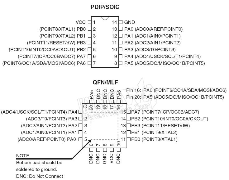
Of course for this assignment I need to know what pin can make what and how it does. Many of the information inside the datasheet is too technical for me so I can read and understand just about 5-10%; for the rest of info I think it will be an incremental process lead by the need of the single information.
I’ve learned what a register is and how it works, that is at the base of every use of a microcontroller.
Registers, in my imagination, are sets of 8 switch (ON and OFF) labeled with weird acronyms; every switch (or group of switches) manages some internal hardware and as a matter of fact they are the most direct interface to drive the micro.
To identify what switch turn on/off we we need two information to refer to: the laber of the register and the index (0-7) of the switch.
All this info can be found in the datasheet, with scheme and explanation of what it exactly does. Anyway it’s not so trivial to read a datasheet and focus, motivation and strong electronic bases are recommended.
Programming
Fuses First you have to set the fuses; they defines how the micro works. You can find all the informations on the datasheet but online there are many fuses wizard: set the options you want to activate and they gives the hexadecimal code to put in the micro. Try with Fuse Calculator
To put this information inside the micro just type
avrdude -p t44 -P usb -c usbtiny -U lfuse:w:0x5E:m
Pay attention: with this string your ATtiny44 will work at 20MHz, but without a resonator it cant, so it would be “bricked” (or locked). If you want to program your micro once and for all than put a flag on the option ‘Reset disabled’ and your micro wil work at the same way FOREVER.
Compiling and flashing When you compile a program you pick informations from different sources, merge it together and translate in binary code to let the micro controller to read it.
In order to be compiled every program in C needs:
- a File.c: it contains the informations about the algorithms you want the micro has to do.
- some Dependencies: “pieces” of program your File.c refers to; some of their functions will be embeeded in the compiled file
and
- a File.make: it contains the “recepie” to “bake” the file that we want to compile, or the info to retrieve all the files (File.c and dependencies) to compile.
Keep all the files in the same folder can be a smart choice to start avoiding any sort of issue.
NOTE: Now we will assume that you have correctly wrote the code (and it’s not trivial at all); you may try start learning C from here http://www.learn-c.org .
Now from the Terminal (or Prompt, or Shell) go to the folder with your program files and digit
make program-usbtiny
If it doesn’t wor try with
sudo make program-usbtiny
So what happen whe you push ‘Enter’?
Actually avrdude reads the following string
sudo avrdude -p t44 -P usb -c usbtiny -U flash:w:$(PROJECT).c.hex
that it finds inside the Makefile; to work properly you have to change ‘PROJECT’ at the first line with the name of the file you want to compile and flash.
This string is quite long and you should rewrite everytime, almost the same, so with this function you con write a shorter one.
When the command enters Avrdude compiles the code and makes a file with .hex extention that contains informations and instructions in machine language. Than it ‘flashes’ it on the flash memory (the non volatile memory of the micro where data stores also if it has no power source).
It will pick the main program and the dependencies specified in the .make file to merge them in a .hex file readable by the machine, and than will automatically flash it on the micro.
Adding a button
I started from the code provided by Neil and added a button to let the led blink when the button is pressed.
#include avrio.h
#include utildelay.h
#define input(directions, pin) (directions &= (~pin))
#define output(directions,pin) (directions = pin)  set port direction for output
#define set(port,pin) (port = pin)  set port pin
#define clear(port,pin) (port &= (~pin))  clear port pin
#define pin_test(pins,pin) (pins & pin)  test for port pin
#define bit_test(byte,bit) (byte & (1  bit))  test for bit set
#define led_delay() _delay_ms(100)  LED delay

#define led_port PORTB		sistema per scrivere sul pin
#define led_direction DDRB	sistema per inpostare se è input o output
#define led_pin (1  PB2)	bitmask della portB, pin2
#define but_direc DDRA		sistema per impostare la portA è input o output
#define but_port PORTA		sistema per scrivere sui pin della porta A, od abilitare il pull up
#define but_pin (1 PA7)	bitmask della portA, pin7
#define but_read PINA		sistema pe' legge'

int main(void) {

	main

	set clock divider to 1

CLKPR = (1  CLKPCE);
CLKPR = (0  CLKPS3)  (0  CLKPS2)  (0  CLKPS1)  (0  CLKPS0);

	initialize LED pin

clear(led_port, led_pin);
digitalWrite(pin,LOW);
output(led_direction, led_pin);
pinMode(pin, OUTPUT);


INIZIALIZE BUTTON
set(but_port,but_pin);			//activate pull-up internal resistor
input(but_direc, but_pin);		//set the button pin as an input

while(1){				 main loop
	if (pin_test(but_read,but_pin)==0) {	//verify a condition

		set(led_port, led_pin); 			//if true do this (put Vout on the led_pin)
		led_delay();
		clear(led_port, led_pin);			//if false do that (turn off the led_pin)
		led_delay();
	}
}
Download button
Extras
An “easier”” way is to use an Arduino IDE and board as an ISP programmer; it may take more space due to its libraries, but its also more straightforward.
Here is explained far better than I can.
http://highlowtech.org/?p=1695
and here a series of videotutorial realy well explained about WinAVR
https://www.youtube.com/watch?v=bEfjFJlrGxs
www.newbiehack.com
At the end of the day you have to remember many things, but just few really counts
1. everything you may ever need search on Google
1. you may just copy’n’paste code, or strictly follow a tutorial, but at the end you have to deeply understand what you’re doing in order to do it on your own without any support
I’ve to say that has been very hard and frustrating to afford this assignment. It may seems simple and straightforward, and at the very end the toolchain is indeed, but becoming confident with boolean operations, registers, a debug and a lot of issues is not trivial at all. Obviously I’m still not as confident as I wish, but it will came with time and practice. The hardest part is the motivational one: not being able to keep in mind simple concepts, having troubles handling some simple logical relations but nonetheless being able to follow the process when explained exept being unable to repeat it autonomously has make me feel incompetent. The truth I came along is that playing something for the first time with a hand tied behind my back (I tried just “the hard way”) is the fastest and surest way to lose sprint, enthusiasm and motivation, mostly if the output is “abstract”.
Special thanksgiving to Carlo, Francesca and Giulio to help me with their time and explanation skills :)
Some more resources in italian and in english I’ve found online
AVR Simulator IDE http://www.oshonsoft.com/avr.html
GUI Software for USBasp based USB AVR Programmers http://extremeelectronics.co.in/avr-tutorials/gui-software-for-usbasp-based-usb-avr-programmers/
AVR8 Burn-O-Mat: a GUI for AVRdude http://avr8-burn-o-mat.aaabbb.de/avr8_burn_o_mat_avrdude_gui_en.php
Leonardo Miliani’s blog
http://www.leonardomiliani.com
Daniele Alberti’s Blog
http://www.danielealberti.it
Logica Programmabile
http://www.logicaprogrammabile.it/arduino-uno-bootloader-chip-atmega328/
Timer Interrupt
Timers are a very useful tool to manage temporal events, such as measure the duration of something, like the time a led has to stay on or off. There is some hardware inside the micro that simply counts clock cycle, so if we know how muck cycle per second it makes we can count time (in seconds).
Inside an ATtiny44 there are 3 timers, 2 works at 8bit and so they count max 255 values (cycles), 1 works at 16bit and so it counts 65535 values (cycles). When they reach theyr maximum value they start over from zero, so we need a variable that increments each time the counter reach its max value.
In many cases we prefer to count time in seconds instead of cycles, so we have to make just some math.
To reduce clock frequency I used the maximum prescaler (its value can be 1, 8, 64, 256 or 1024).
reduced frequency (cycles/sec.) = clock frequency / prescaler
The clock frequency is set by the fuses; the prescaler is just a value you choose.
16bit counter duration (sec.) = 16bit counter max value / reduced frequency
so this way we know how many seconds it takes to reach the max value of the counter. Now the last division to know how much cycles are needed to count 1 second
cycles per second (cycles) = 16bit counter max value (cycles) / 16bit counter duration (sec.)
This value is very important because is the value we have to use to measure one unit of “human” time and we’re going to use it very soon.
To set the timer I’ve followed this tutorial found on fabacademy website, but I changed some value like clock (1000000) and led pin (PA8) and added some code in the while(1) cycle.
#include <avr/io.h>
#include <avr/interrupt.h> // notice that we have swapped libraries, from delay to interrupt

	ISR(TIM1_COMPA_vect) { // this function is called every time the timer reaches the threshold we set
		PORTA ^= (1 << PB2); // toggle the LED
	}

	int main (void) {

		DDRA |= (1 << PB2); // set LED pin as output
		TCCR1B |= (1 << WGM12); // configure timer1 for CTC mode
		TIMSK1 |= (1 << OCIE1A); // enable the CTC interrupt

		sei(); // enable global interrupts
		OCR1A   = 976; // set the CTC compare value
		TCCR1B |= ((1 << CS10) | (1 << CS12)); // start the timer at 20MHz/1024

		while(1) { // main loop - do anything you like here!

		}
}
To set the timer follow the datasheets; the following images are taken from oscarliang.net and from the datasheet.


So now a led can blink (and any other event can occur) just when is triggered, without waiting and stopping the main program with the delay.
Here below some more reference I’ve used to understand how to set a clock
OscarLiang.net blog
Arduino Timer Interrupt by amandaghassaei on Instructable
