David Montenegro
FAB ACADEMY 2015
Final Project | Assignments | Download | About | Contact
02_04 Computer-aided Design
On wednesday 04.02.2015 we’ve got the second online lesson with Neil Gershenfeld.
The next lessons can be found on the Fab Academy account on Vimeo.
All the documentation can be found here
For this week the assignment was
**model (draw, render, animate, simulate, …) a possible final project, and post it on your class page **
Set up
Originally my final project was a set of devices to simulate a solar system or a galaxy, but at the end it has changed because of its complexity.
Here you’ll find the experiment focused on the first project.
- Planets: probably they will be represented as regular polihedrons; inside they have a printed case to embed eletronics easly, and a light structure of pillars to stand aside the external faces that can be customized. This module has some parameters like number of faces, diameter and so on, bounded togheter in precise relationships that I’ve to define by functions to allow the parametric generation af new and customizable modules.
-
Pieces: ships and buildings will be made as 2d shapes; they have to be very light in order to stick magetically over the planet and they have also to be recognizable by the planet.
-
Frame: it’s the frame to use if you don’t have a structure to use to hang up the planets: it will be made as 2D shapes to joint together.
What I’ve done
Planets
I started exploring online resources about OpenSCAD. It is not an interactive modeller. Instead it is something like a 3D-compiler that reads in a script file that describes the object and renders the 3D model from this script file. This gives you (the designer) full control over the modelling process and enables you to easily change any step in the modelling process or make designs that are defined by configurable parameters.
I started googling “polyhedra openscad”. I report just the most interesting records
-
The Conway’s Game of Life In this video John Conway explain the rules of the classical Game of Life. It wont be usefull using OpenSCAD but I liked it and I think I’ll eventually take inspiration from it for further developments of rules set.
-
The Wallace Line In this tumblr I’ve found a lot of OpenSCAD experiments really inspiring. On his website I’ve found something interesting to start like scripts for OpenSCAD to generate polyhedra.
I’ve followed some Patrik Conner’s tutorials and Wikibooks and I’ve realized the potencial of OpenSCAD: it works well for mechanical part, maybe heavy computation tasks, but to design something like what I’m keeping in mind I need something more interactive to define the correct shape.
To draw a poligon it requires to enter manually the coordinates of every single point and set the order to define the normal direction.
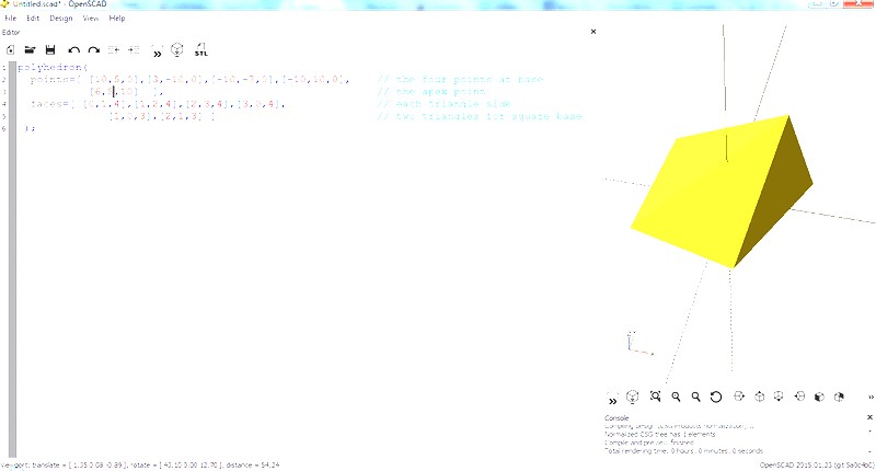
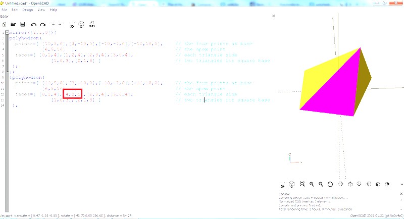
This kind of approach let you perfectly understand how meshes work, but it seems to not be proper to produce a parametric and generative model to allow game developers and players to easly self produce different models of planets.
I tried also Grasshopper, a free plugin for Rhinoceros. This tool is based on a visual programming GUI that let you manage complex data geometries faster. I’ve found Wavebird, a topological modeler that contains many of the known subdivision and transformation operators. Instead of doing the work repeatedly, or sometimes using complicated scripts, this plug-in reconstructs the shape, subdivides any mesh, even made by polylines, and helps preparing for fabrication.
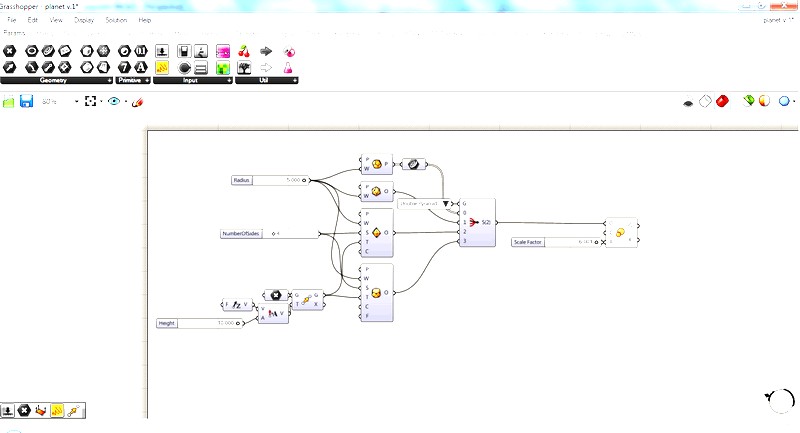
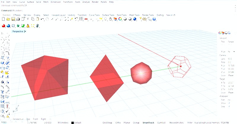
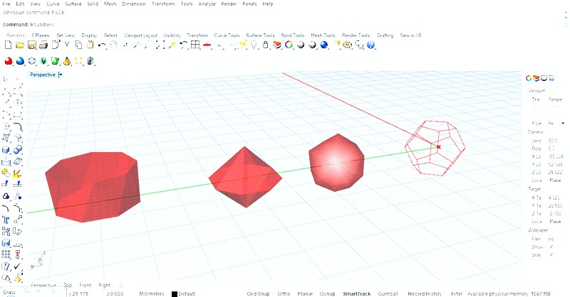
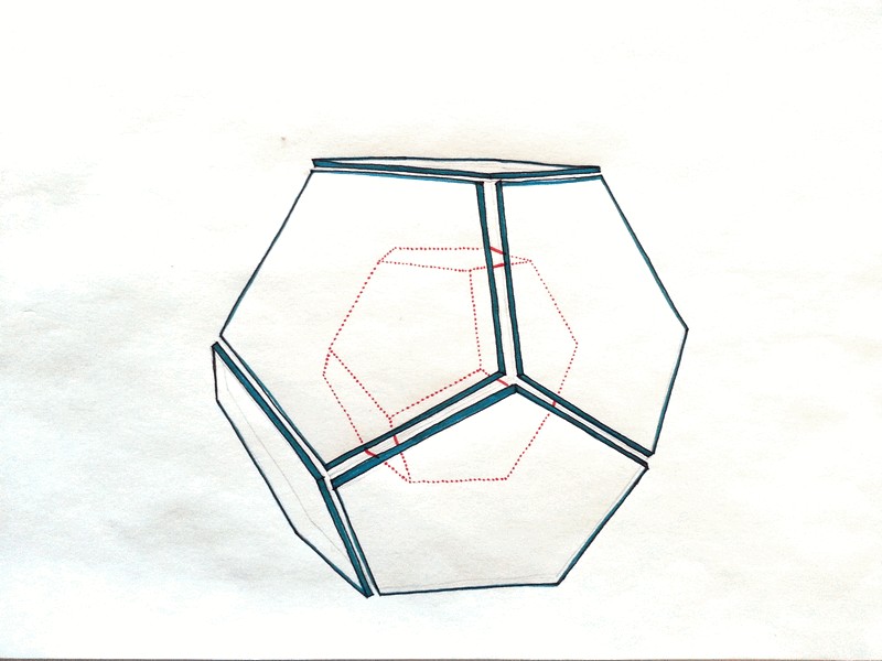
Polyhedra are just the base of the model and with this tool is fairy easy to manage their properties dynamically trough native sliders. I’ve setted four geometries: icosahedron, dodecahedron, double pyramid and anti-prism; unexpectedly the dodecahedron has just edges and not the meshes as output. I think it depends by the shape of its faces: meshes can be triangular or quadrangular, but not pentagonal, so probably, due to a lack of informations, it’s impossible to compute the faces.
To correctly place the pillars over the faces I’ve to find relative planes and set the origin on the center of every faces. This step is not so intuitive as it can seems at first sight.
I’ve to remember that I’m working with polyhedra with nf number of faces, np number of different polygons and each of ne number of edges, so I’ve to set at least three basic parameters.
At this stage I prefer to manage single cases to produce a prototype, but in the concept
The next step is to draw a sort of simple pillars to physically scale the planets physically maintaining always the same structure and use difFerent material to customize every single planet.
I started drawing on a triangle base to be compatible with the most common shape of faces, but it is not well suitable with other type of faces (i.e. squared or pentagonal). So probably the best choice is to start from a circle.
I used this shape to start designing the “ship” and the inner structure of the planet.
Sketch
I know that the piece “spaceship” has to be very light, simple and not strictly representative in its shape. The idea was quite clear: a simple cube.
So I’ve made some sketch to figure out how the joints may work together and then I started working on Grasshopper to build a tool that allow to set dimensions, material and tolerance and spits out the whole set to make a “cubic spaceship”.

Grasshopper
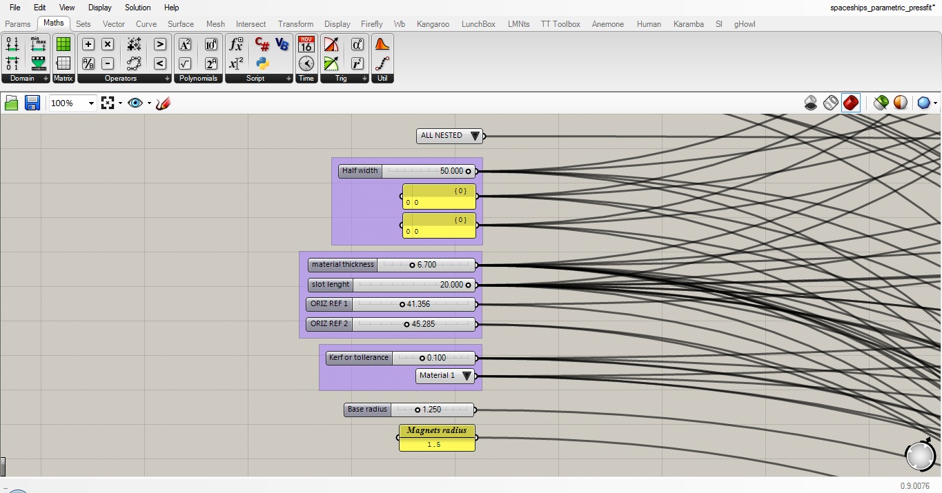
The Grasshopper definition has some minor parts, like ‘base rectangle’ or ‘base slot’ and 4 main branches, one per piece, plus one more to parametrically define a puzzle joint to eventually add upgrades and accessories to the piece.
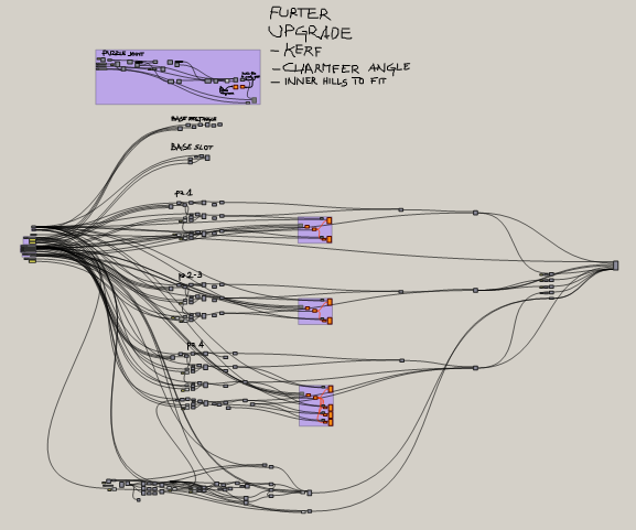
- On the left side you can find all the parameters that defines the joints; grouped this way they allow to manage all the definition from just one site.
-
At the center the definitions of the different pieces (piece 2 and 3 are the same).
-
On the right the filter to show just one piece or the whole kit nested and ready to be cut.
-
The independent group at the top defines the puzzle joint.
HD Grasshopper Definition Image
With Grasshopper I experimented also with 3D, designing the main pillar of the planet.
The structure should be made by a core with polyhedra shape to contain the electronic part, parametric pillars to scale up the planet and customizable outer panels to lasercut or mill with different materials to customize every planet. On the surfaces of the planets magnets provide to retain ships and electrical contacts “reads” the id of the “ship”.
Due to the strong bound between “ships” and planet’s surface and inner structure I started designing the pillar from the “ship” file, using boundary to let the system parts suits together.
The pillar has also some physical and productive issues that defines its shape: it has to be light and stiff and its “ceiling” (even if it has no orientation), has to be 3dprintable without support, so I designed a shape like this.
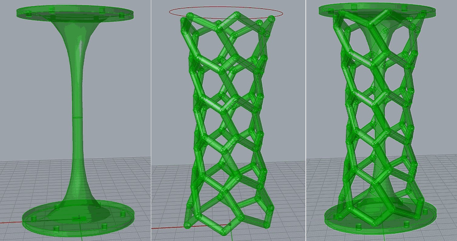
Top/bottom and central part are quite simple surfaces; instead the external structure maybe deserve some words.
To design this structure I passed through several steps:
1. a continuous surface driven just by the edges and the mid-section made with the function “loft”
1. two different and mixed steps, each one with different ways, to subdivide the surface
1. the pipe function to control the diameter of the branches
1. some fine tuning to fix some bug and have a continuous solid structure
This way I can modify its dimensions in a very precise way and also produce many models so I can try to print them to find the best one. See also the 3D print page
Download
strange_pyr_faceflipped
planet_v1
SpaShi_CB_6.7mm_k0.1
Pillar