Click on the links below to go to specific areas of the project
As stated in previous weeks, one of my primary aims was to get a working goal detection system on my table, at first glance I had a few options on how a goal would be detected;
The simplest option (though not one I considered seriously) was to allow the players to hit a button to say they had scored, the display would then show the goal increment. This isn't ideal because it doesn't allow for fair play if someone presses the button more frequently.
This is effectively the same as the option above but would be automated. This option relies on copper strips that on one side are connected to the switch pin (which is set to internal pullup) and the otherside to ground. The puck would also have a copper strip on the underside which when passes into the goal zone, would bridge the switch pin and ground, thereby registering a goal.
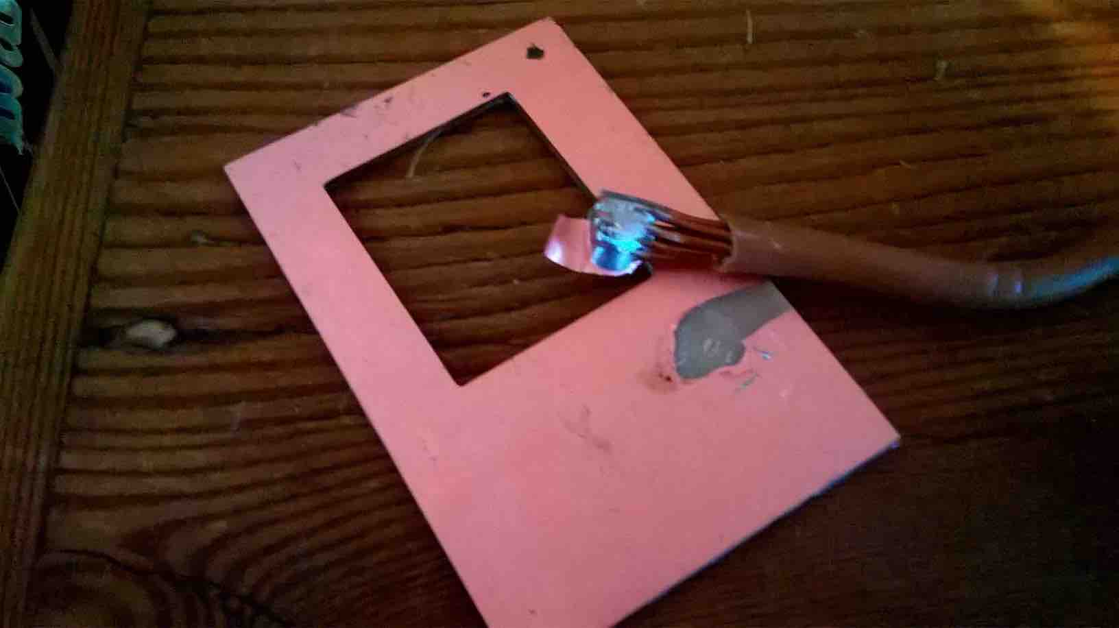
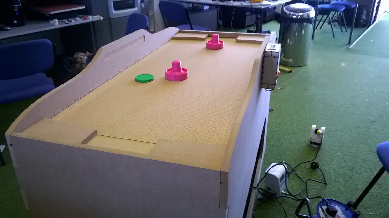
Originally this idea was based around a slot in the table that would allow the puck to enter an external goal zone (as descided in 3D Design below). After much thought, I decided to look at having this methods on the bed itself and not relying on a 3D printed goal zone. Below you can see a protoype of the goal zone
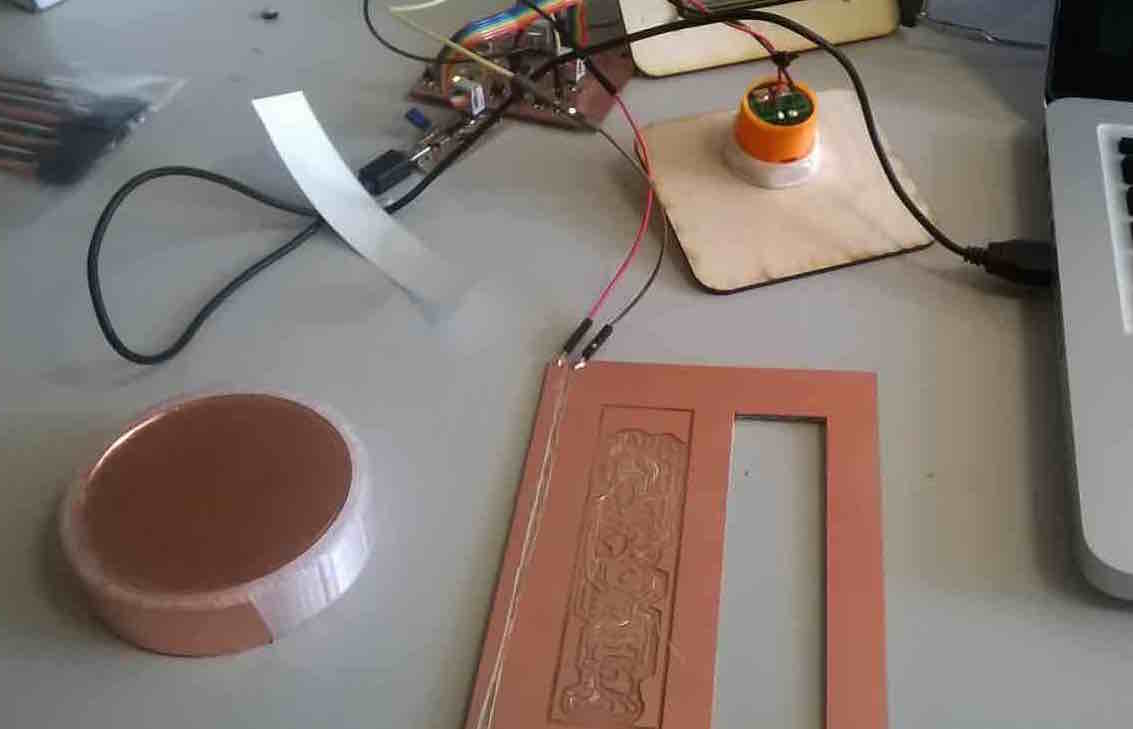
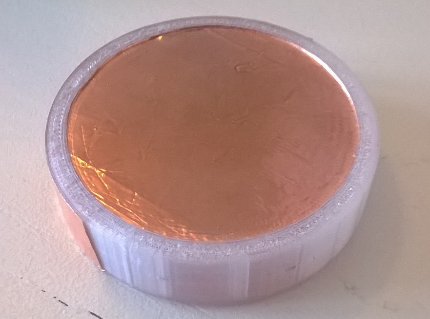
I did play with using copper boards, but I found that the goal detection was not very responsive on the boards as compared to the copper vinyl, so I went ahead with copper vinyl
Using an Infrared LED and detector, I could detect when a goal has passed through the opening. I did some basic tests using FabLab's basic IR emittor and detector to see how effective this could be and found the range was too small for the goal opening size (10cm as compared to 20cm). It was a shame (I thought I took a photo of it) because this method would have been useful. I was also concerned that with an IR method, I would have to enclose the laser to avoid the player accidentaly breaking the sensor path. I was looking for something simpler that allowed me to focus on a simple table design and not one with hidden complexities (this time around)
I flirted with the idea of using a piezo vibration sensor to detect when the puck had fallen through a shaft (high vibration would be registered as a goal) but this required an analog pin to read the piezo speaker and I had already designed my board which was using most of the analog pins on the LCD display. If I was to redesign the board, I would try and leave the analog pins for more suitable uses.
A lot of people around Fab Lab were recommending the capacitance sensor as a method of detecting the puck. If the puck travelled across a capacitance 'patch', it would change the capacitance reading. The only problem with this method at the moment is that the player and the mallet may also give a false reading on the sensor if they pass over it. In order to prevent this, I would have to design a system to cover the capacitance sensor from human error.
In my opinion, I think it sensible to go ahead with copper vinyl as a goal scoring system. My reasoning for this, is that I would like to have a simple build stage of the enclosure, without the complexities of intergral IR parts of dropdown goals which might not work straghtaway. With the copper vinyl, I can get a working prototype going very quickly, and then later turn to make the goal detection system more intricate
When I began this research, I had no idea how a normal air hockey table worked in regards to the air flow. In fact, it is still difficult to obtain strong evidence on how Air Hockey companies achieve such a consistent air pressure across the whole bed. In the end, I was of the conclusion that the big tables use a compressor fan to achieve the uniform results but a quick google search shows the prices of these can range from a few hundred dollars to thousands. Not an option...
I began looking for alternatives. I considered an array of PC fans as a bed but after a quick trial with a 12V 120mm^2 fan, I was not convinced of much. I began to payclose attention to the CFM (cubic feet per meter) outflow of each respective fan. I found an average PC fan would push 80 CFM per minute. I needed some big inspiration and it came after I asked all of my Fabclass mates across the world.

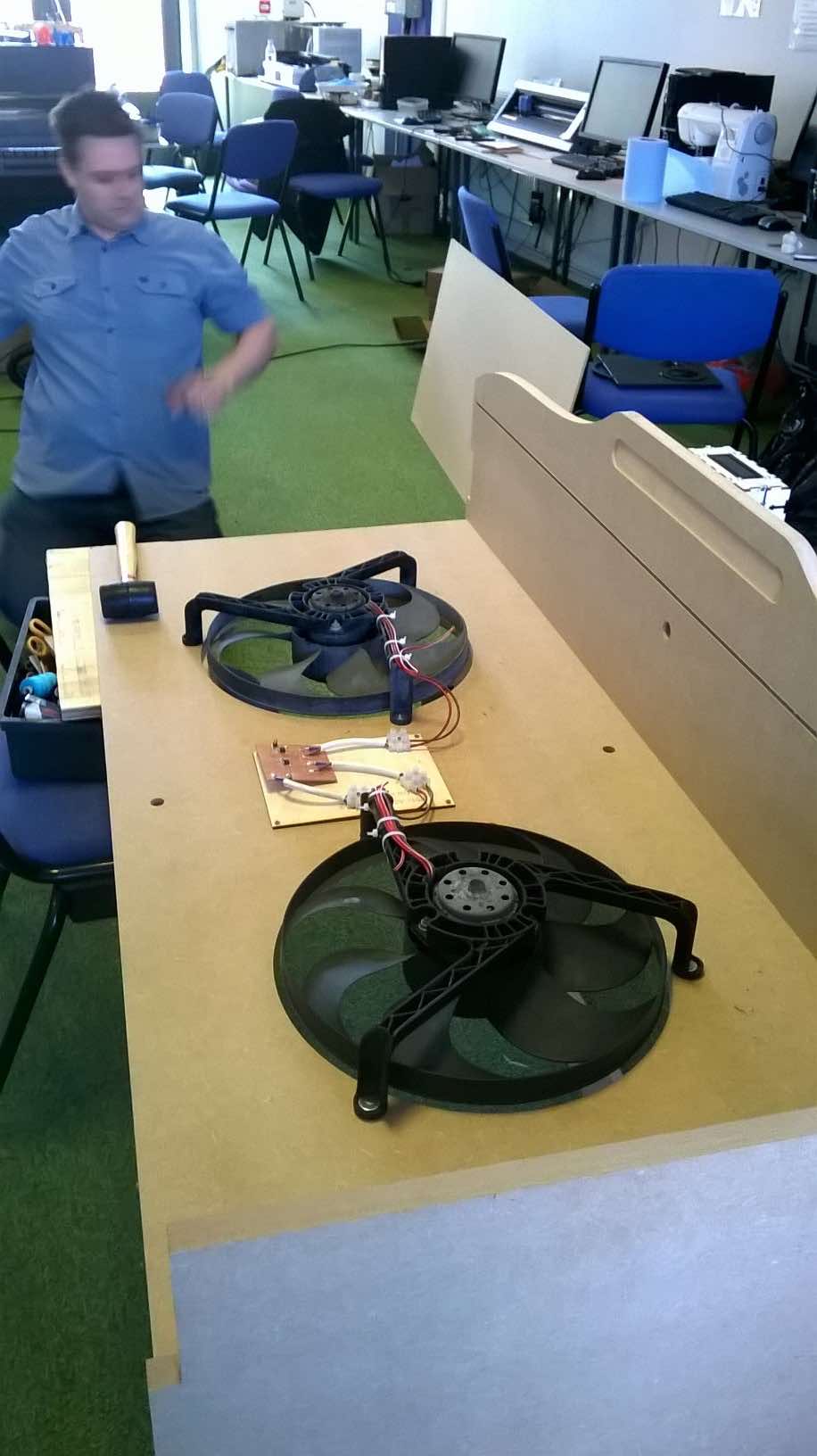
After great inspiration from Sergio Subrizi on the class email, I started googling 'Car radiator fans' and was pleasantly surprised. A typical car radiator fan would produce ~2000 CFM per minute. I went down to my local scrap yard and took away a free one to play with. I was hooked on it, it produced a great air flow. See the video below for demonstration.
Once I knew the power of one of these fan, I went and ordered a replica of it so I could use two of these fans on the table. This was not based on any scientific equation, instead I had a feeling of the area it could cover from the prototype development.
3D Design is used in various stages in the final project so I will break down it into individual components
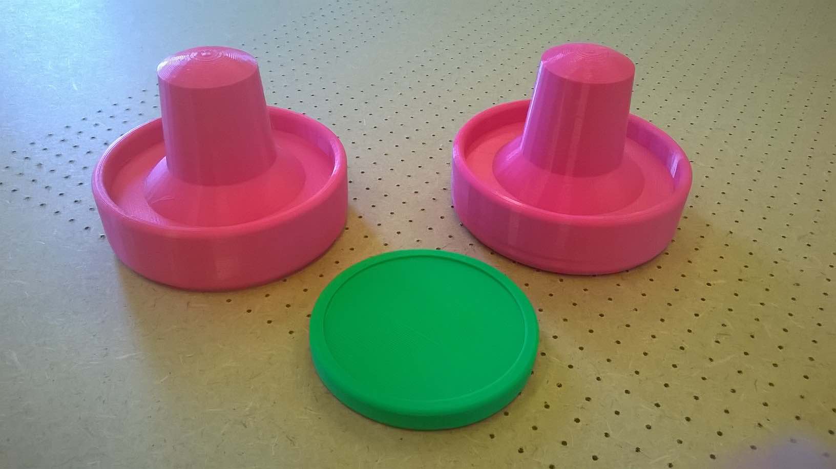
These were the simplest part of the project because it was simply an exercise in 3D designing and they couldn't differ far from the original products.
This is simply an extruded cylinder with filleted edges and a reccessed top. The underside of the design will have a layer of copper on which will be the bridge for the switch. My original design was a 20mm high/80mm diameter puck but after playing with the design, I believed it to be too big and not realistic enough so I went with a 10mm high/80mm diameter puck. This felt more realistic and will probably have a better glide due to a reduced height. This was printed on my 3D printed and the linked files for the puck are at the bottom of the page
The mallet is the device the player uses to hit the puck. The mallet must feel right to hold (ergonomics) whilst not being to heavy or fragile (it's going to get a beating I'm sure).
Using home utunsils such as saucers, I deemed what was the right size for the mallet. I did an original design using Solidworks and did a rough 3D print for hand-feel. This design had a couple of issues such as no finger guard and the shaft was slightly too short for a good ergonomic grip.
I went back to the design and added a finger guard which was a raised edge with equal filleted edges on either side. I then raised the shaft lentgth and removed the circular pattern I added on the first attempt (this didn't add anything). I then did a rough 3D print with 10% infill to test the design. Apart from cosmetic issues, the design was just what I wanted. My aim is to now use casting and molding techniques to create some great looking mallets but the option of 3D printing them is still available. UPDATE: This has now been 3D printed using PLA with 80% infill, each mallet took 2 days to print!
I originally planned and designed a basic 3D model of a goal area in which the puck would come out of the enclosure design and onto a platform which the goal would be read. I 3D printed a scaled model of the goal but I quickly became concerned with the player being too close to the goal zone which could interfere with the readings whilst the player being too far away from the game to play properly. As discussed in Puck detection above, I opted to lose the extra goal area in favour of an enclosed goal area on the playing surface (therefore no 3D part will be provided for this)
So for my final project, I wanted to:
I debated with myself over what I would need to meet these conditions. I wanted to try and achieve this through Neil's mantra of linking smaler boards together to create a network of devices, each doing their own task when called upon. I had experience of this with networking and communications week but I was also concerned of about the memory of the attiny44a, as the libraries used in Arduino can use up all the available memory very easily.
I wanted to use Arduino to write my code as I believe I could learn most from that method in the long run. I could have got a lot of help writing all my code in C whilst also utilising a network of attiny44a boards to meet my final product needs, but I would not learn as much from the process than trying to write it all in the Arduino IDE and getting help with the final elements.
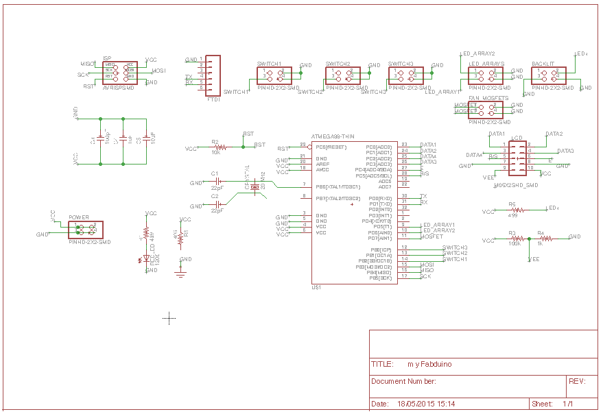
I decided I wanted to try and make something bigger, so I chose the attmega328p board. My first reason was because the board had much more memory and pin outs available for my project, but the big reason I chose to make this is because I wanted the chance to make my own fabduino/arduino board and understand what is required.
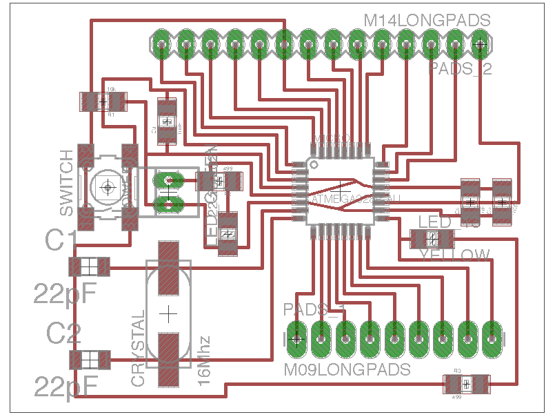
I have paid close attention to the work of Danielle Ingrassia from Italy who took great advantage of a flex laser cutter to create circuit boards. Daniele created the 'Satshakit board', an evolvement of the fabduino and a board in comparison the Arduino Uno pinouts. I began by taking Daniele's Eagle file and creating my own board that would meet my needs of having multiple attachments. I was very pleased that I had been able to create my own board using Eagle so easily.
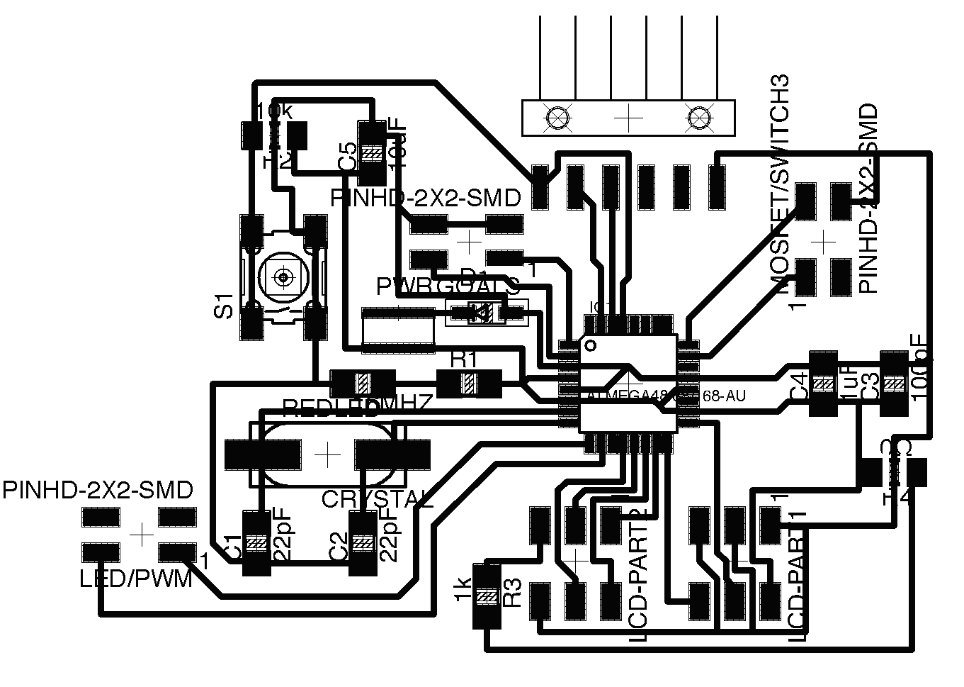
I then took this board design to James (our local electronics pro) who brought a few issues to my attention with my original design. Firstly though I had a FTDI connector for communication, I had no ISP header for uploading my code easily. I was originally planning to do what Daniele does with his board and place individual jump leads on the ISP pins to create a connection, but this was not ideal and so there came a mission to add one to the board.
I also was not taking full advantage of all my pins on the board, as my PWM pins were taken up by non-PWM devices. James suggested I look at what PWM pins were on the board and use them for my LED arrays. I also chose to get rid of the reset button as James didn't see this being vital to the operation of the board. Finally James suggested making the connectors line up together for aesthetics, so back to the drawing board I went!
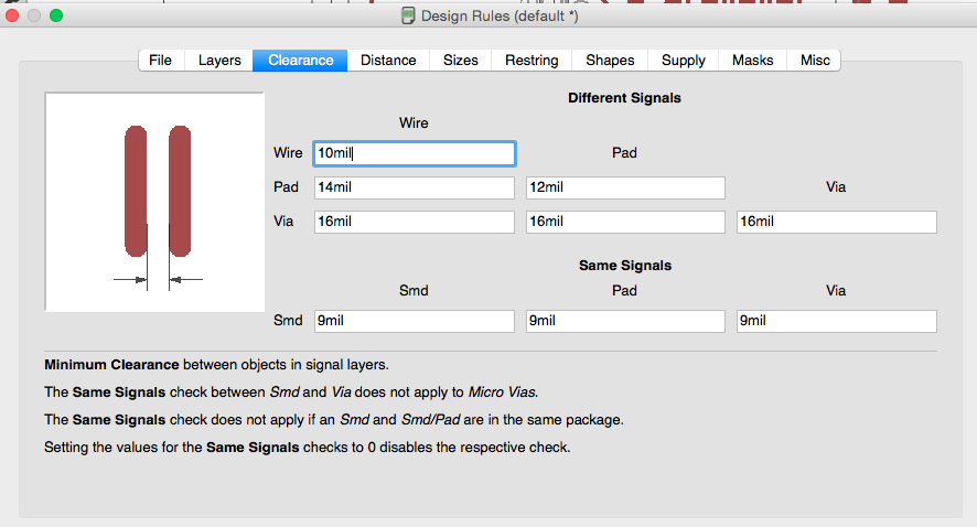
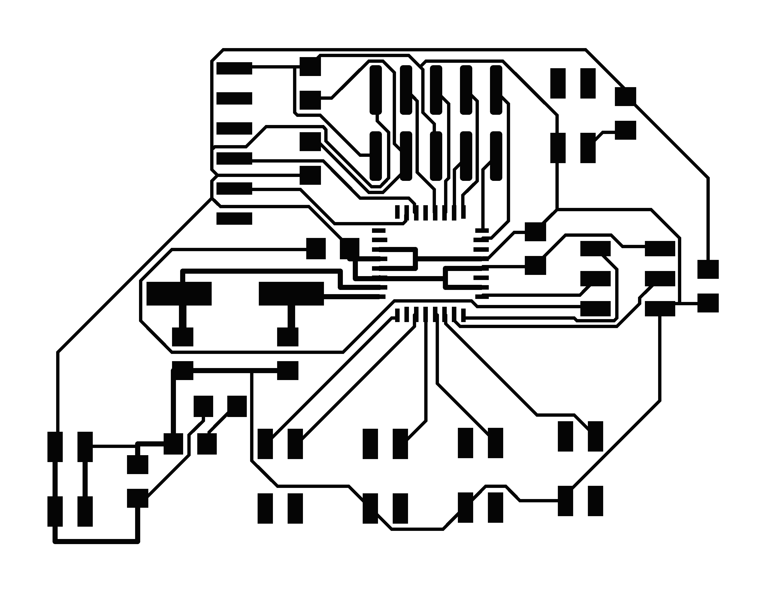
If I had to give some advice to someone using Eagle, I would suggest not using autorouter! I found the autorouter tried every random route to get all the routes. I kept going back to the design rules to adjust the space between wires, pads and vias. I learnt quite a lot from this method, and the best way forward was to rearrange my board and logistically work out all the traces. This way I could control the route without it looking like a mess and not going between resistor pads (an annoyance of mine). The only via I had to do was for one of the ISP headers, but this was so easy, I would probably look at doing this for more connections in future.
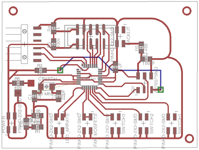
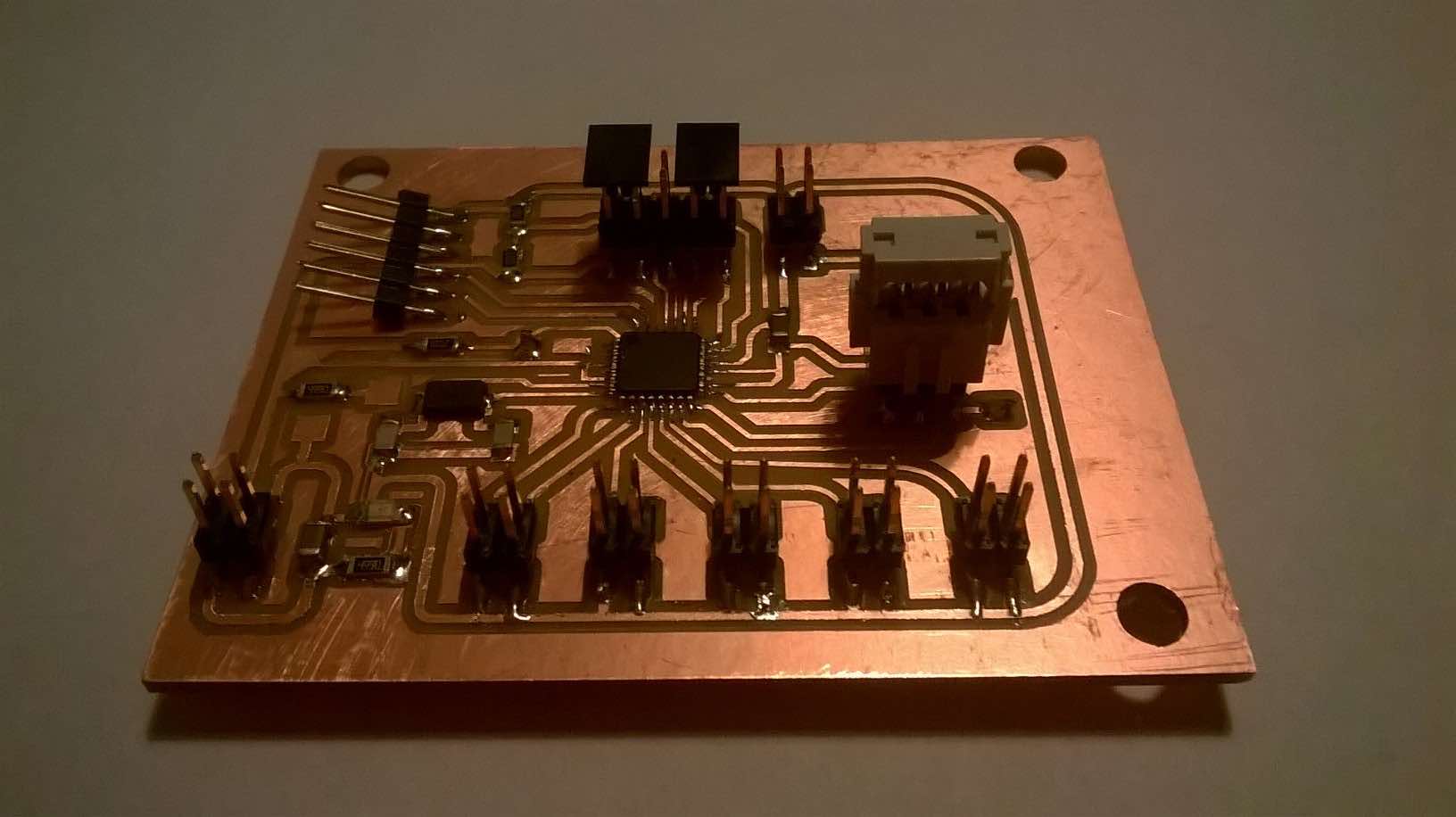
After much editing, I had a final design ready to mill. It was only after taking my design to fabmodules.org where I could see that a few of my connections were not going to be milled because they were seen as one. I took my design to 'Gimp' where I had to remove parts of the traces in order to get a good result in fabmodules.org. It would be interesting to see how much the flex lasercutter needs between the traces inorder to get a good finish. Once the board was complete, I quickly assembled it but noticed the 2X2 connectors didn't fit very well (tight fit), so if I was to remake the board (hopefully I don't!), I would change this to have a larger gap.
Despite having a board with pin headers slightly too close together, I went ahead and started testing the board for any issues. I first tested the board by putting 5v across the power connector (I didn't add a reverse polarity protective diode). This made the green LED light up and no smoke came off the board so this was good!
After awhile of testing the board, I struggled to upload any test code. I tried using the group email to try and find a solution but I wasn't successful, I was starting to think that my board was not designed properly, the only way I had differed from the satshakit board was that I used a 20Mhz crystal instead of the 16 Mhz crystal. I replaced my 20 Mhz crystal with a 16Mhz crystal I purchased and tried again, but no success. After speaking with James, we were able to upload a C code example which did a basic blink so I was comforted that my board was OK. Despite this, I didn't want to spend the majority of my time writing my code in C as I beleive I wouldn't get as much learning out of it compared to Arduino IDE and it's libraries.
I finally found the solution which was in the Arduino IDE of selecting 'Upload using Programmer'. This method ignores the FTDI connection (which I still can't tell why is not working) and using the ISP header. This allowed me to upload code, and when I had selected the right pin names, I could upload my code. I could then attach my FTDI cable to see the serial monitor.
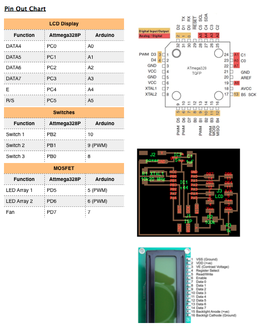
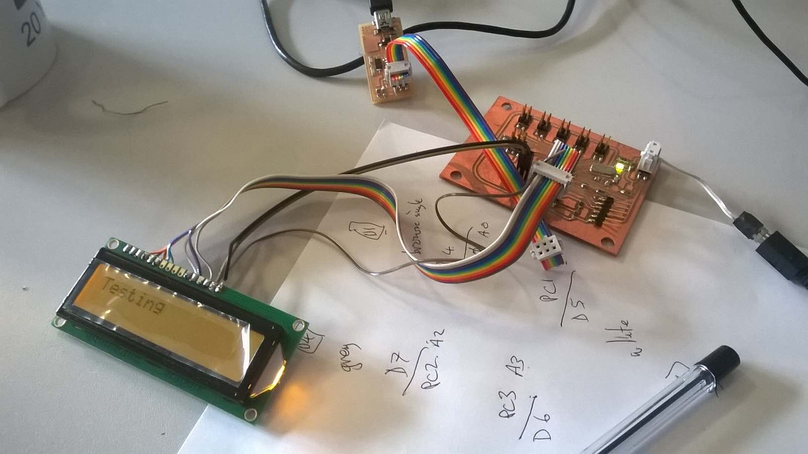
This is the pinout diagram I made showing how I connected all the inputs and outputs to my fabduino. The LCD took some work to get working as I believe the use of analogue pins was causing issues with the liquidcrystal library but then a test with a continuity tester showed thay one of my pins was not making contact. After laboriously trying to solder a single strand of wire, I managed to get the screen working.
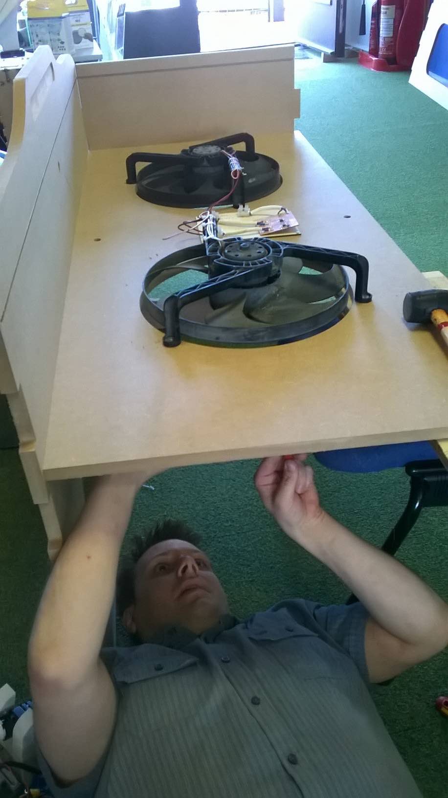
As mentioned above, one of the goals I wanted from this project was to control the fans using my Fabduino. Before I looked at how I could do this, I decided to hook up one of the fans through the ammeter to see how much current it pulled (a brief test a couple of weeks earlier showed around half an amp.... so wrong). Once I hooked up the ammeter in series with the load, I was able to get an accurate reading.
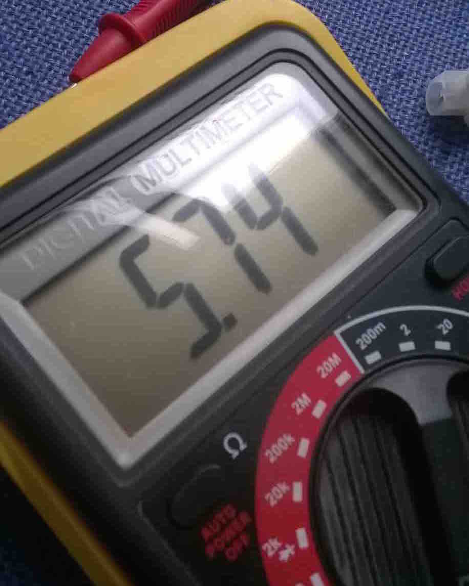
Well I couldn't have been more wrong, it goes to show, make sure you test something yourself and not rely on others wiring. The current started at around 12 amps but instantly drops to around 6 amps when steady. This means, with 2 fans I am going to have to control around 12 amps of current. This is a big ask.
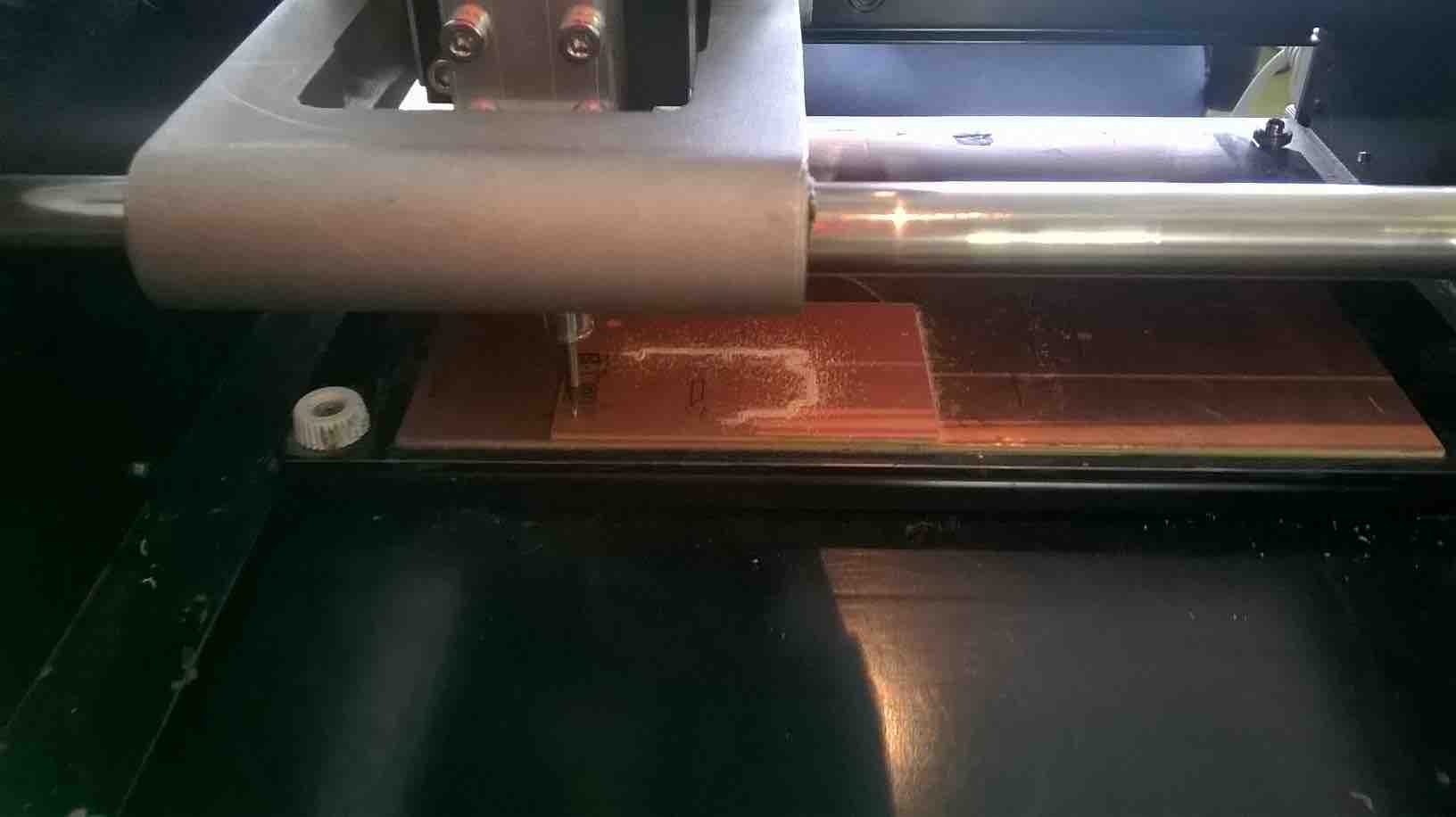
I decided to use the 16A mosfets to control the 2 fans (technically they can be controlled indivudally but they will both turn on at the same time). I gained some advice from James on designing a mosfet board and I went ahead and created it. Milling was fine but needed to drop to 0.15mm for a good cut.
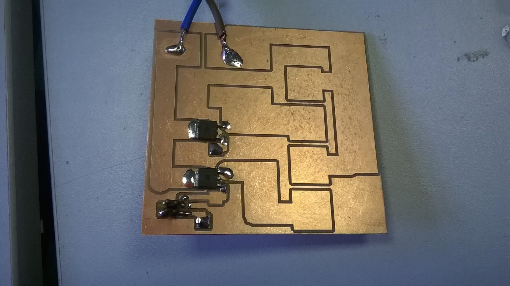
After milling and assembling, I tried to hook up a simple LED array across the load without anything attached to the gate. Unfortunately the LED's stayed lit up which meant either the MOSFET's were damaged, or I had been a numpty and put the drain and source on the wrong way around. After some assistance from volunteers at FabLab (Dave & Peter) we worked out that I had indeed got them the wrong way around (I always thought the large pad on the back of the MOSFET would naturally go to ground but it depends on the configuration). I r ipped up the tracks and soldered wires on in the opposite direction which made the MOSFETs work! See the video below on testing the MOSFET with the LED array. In order to effectively turn on and off the LEDs or fans, it is essential that there is a common ground between the MOSFET GND and the microcontroller. I have a powersupply which will provide the common GND but I may add a GND connection between the MOSFET and microcontroller to ensure this occurs.
In this YouTube video, you can see the LEDs being turned on and off by changing the gate pin from high to low (not recommended)
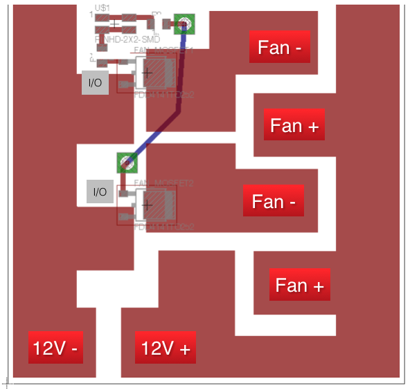
Here is how the final boards work. This needs some work to make it work properly (see project conclusion notes) so do not follow this precisely, just use it as guidance.
I played around with different cables attached to the board (there is a lot of current going through the board). It took a while to solder but I managed to solder a shower cable to the board, which did hold for quite a while but does add a lot of mechanical stress which can rip it off the board. I instead opted for a 13A cable which was flexible but strong enough for the current drawn.
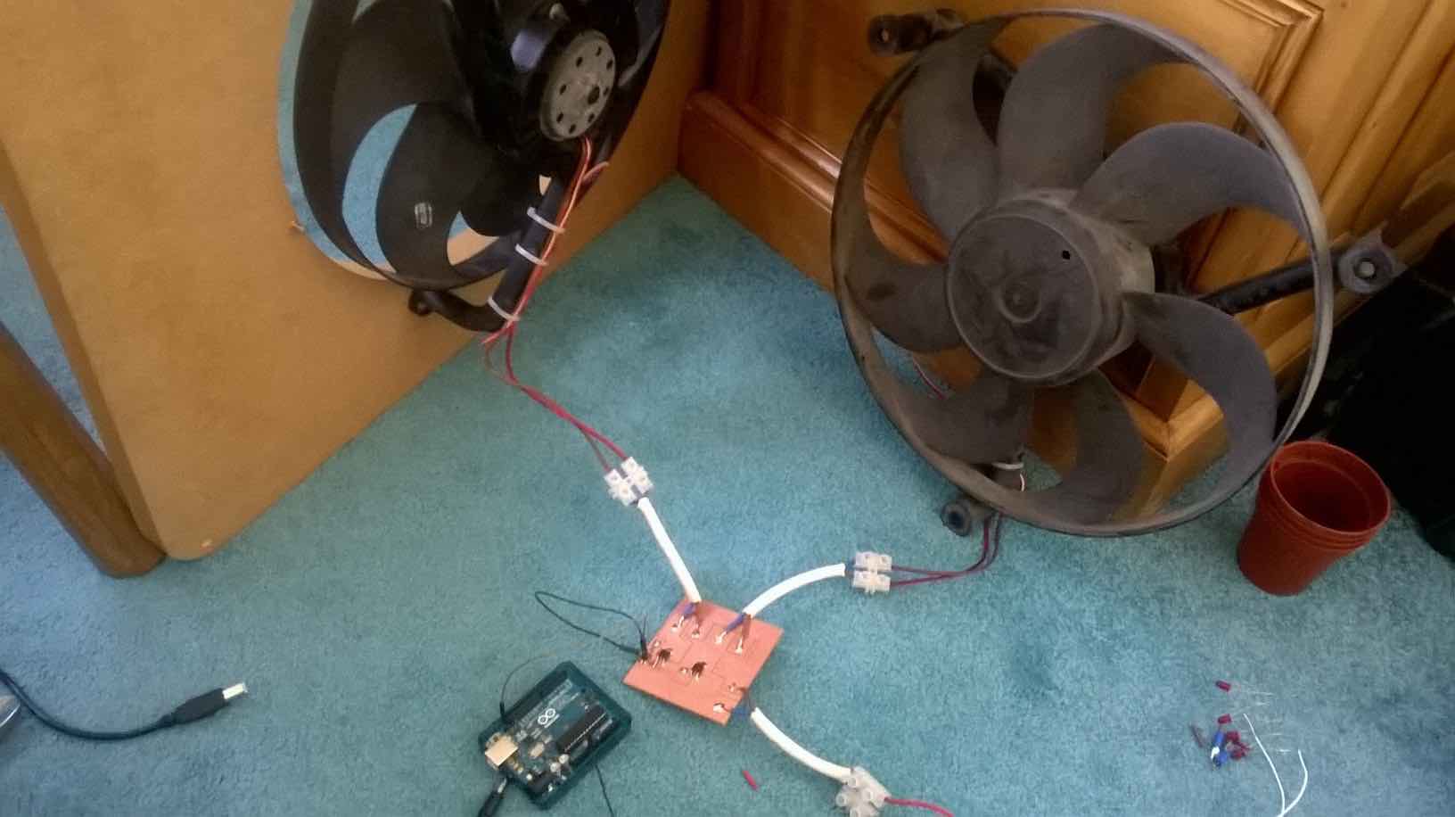
I did a brief test with my Arduino by hooking up both fans and turning them on and off every 60 seconds. I also added a common GND between the Arduino and the GND of the 12V supply. This tested worked well.
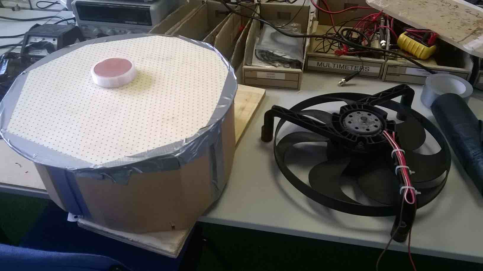
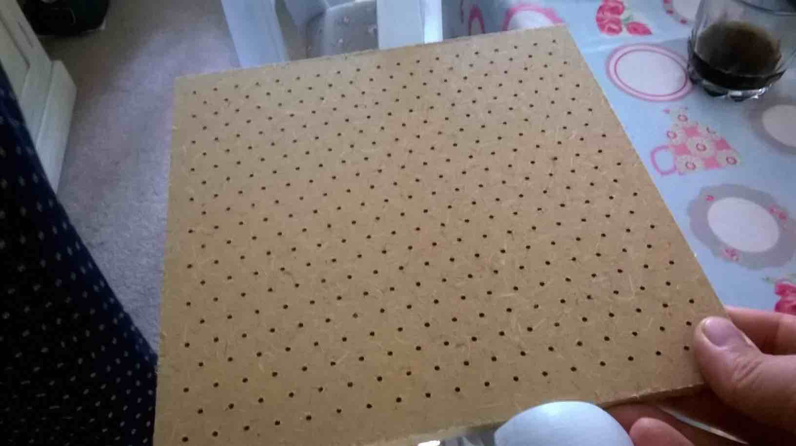
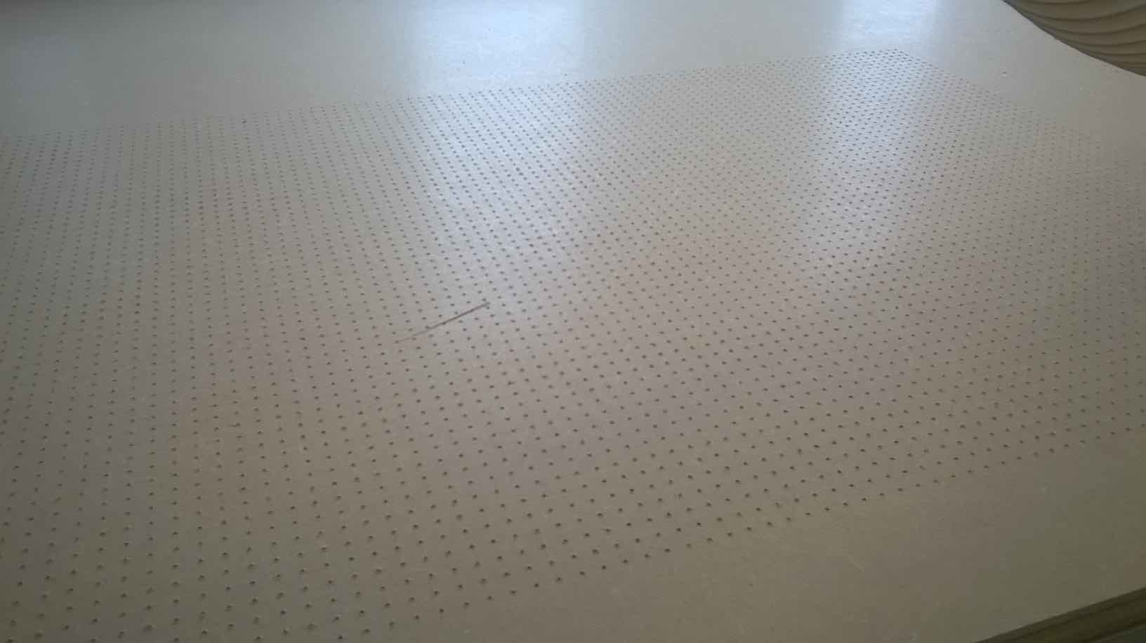
Above you can see my original testing of the car radiator fans. I created a cardboard enclosure and placed a lasercut hole design (1mm holes, 10mm apart) on top. There were issues with the air leaking away from the surface but overall it did show that a puck would glide on the surface when the fan was on. I would say this was quite a success!
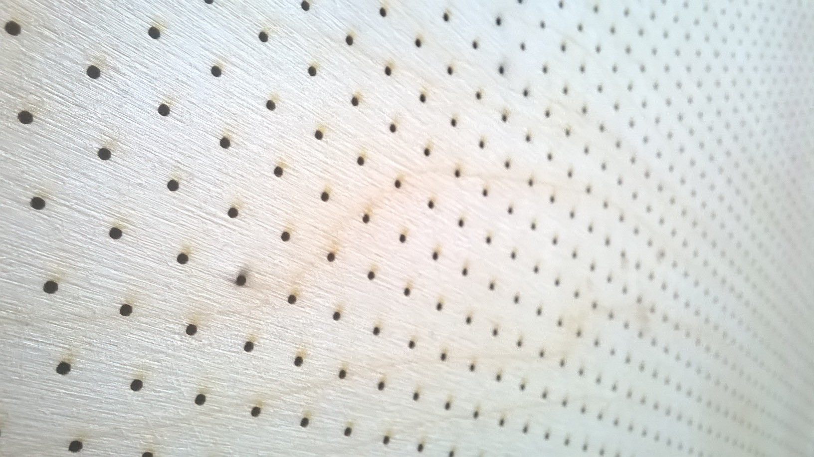
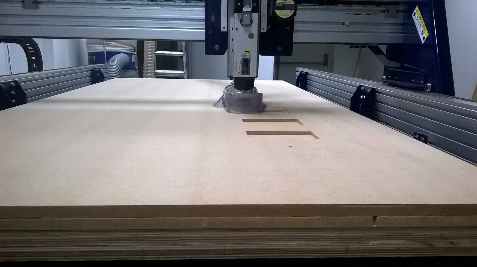
Knowing that I couldn't use the laser cutter to do the air holes for the air bed, I did a test on the shopbot to see how it fared. I was quite pleased with the job but I had to increase the hole size inorder to accomodate a larger bit, but this worked well. The only issue from this test was the roughness caused underneath. I believed this was caused by the drill bit not going down far enough to leave a good finish. This is something I can anticipate in the final production.
I also looked at very thin designs for the air bed surface (not too deep as it would interfere with the puck level) but I was not keen on the look. If I was to do this project again I would look at an acrylic sheet as a bed because then I could light it up with LED's.
When I was having trouble uploading my test code to my Fabduino, I was worried that the only solution would have been to upload code by writing it in C. I would have found this a great learning method but I believe I would learn more from writing most of the code and getting assistance in the final adjustments. After working out that I had to upload to my board by pressing 'Upload using Processor' in Arduino, I started to write my code.
My final code is available in the download section at the bottom of the page. Below I will show you snippets of the code and how it helped to make my code work. Please note the Fan Output is not included in this section because I did not find a suitable solution in the time period (I know what I need to do to make it work next time), but this is easy to add in for anyone building the project.
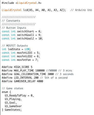
In the first part, I declare the pins required for the LCD display. This is a 6 pin library for Arduino which includes R/S, E, and 4 data pins (see above for Pin Out Chart).I then declare constant inputs & outputs, define certain values and use enum (enumerate) to create the order of the game states.
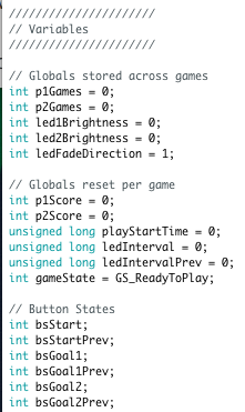
I then declare my variables including games won, ledBrightness and direction. I also state the first GameState as GS_ReadyToPlay.
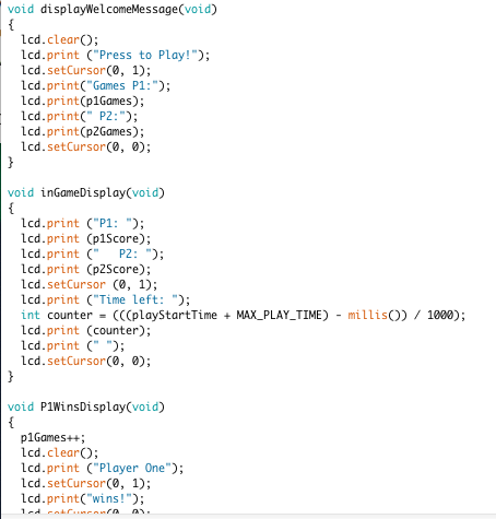
I then created a list of LCD Messages which are called at various points in the game such as P1 Wins, or Draw.
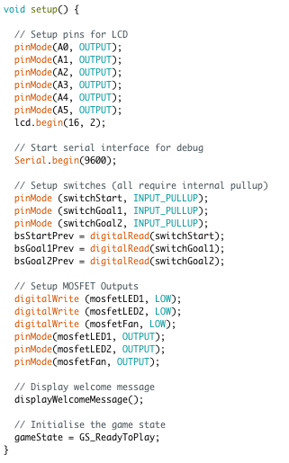
Because I am using the analogue pins for my LCD I have declared them as well. This may not be completely necessary but it was added near the start of testing. I then begin serial communication which can then be read by my Processing App (this needs adjustment to make it work seamlessly with my new code). Pin modes are declared and digitalWrite fans and LEDs low. The display welcome message is shown.
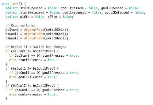
This is where the code gets interesting. Before we get into making the code do anything, we setup several boolean operators which look for button presses. If a button is pressed and this was different to the previous time round, then change the boolean to TRUE. The boolean then gets reset at the bottom of the code (not shown) to match current and previous. This will run in the loop all the time, always checking the state of the buttons. It will then be the code below that will decide to do something if these change.
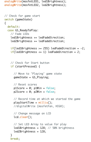
Now the buttons are being checked, we enter GS_ReadyToPlay. In this state we are fading the LED's by using analogWrite to PWM them. Because the analogWrite only goes up to 255, we can just tell it to add 1 or take 1 away and it will remain in the 0-255 or in reverse. We then add an if conditional which looks to see if the number has reached or gone over 255, if so, make the fadedirection reverse.
Now we are ready for the start button press. When we begin the game, the game state changes to GS_Playing but before we get to that; the scores are reset and the LCD is cleared and the LEDs are set to 50% brightness. We are now ready to go into play mode.
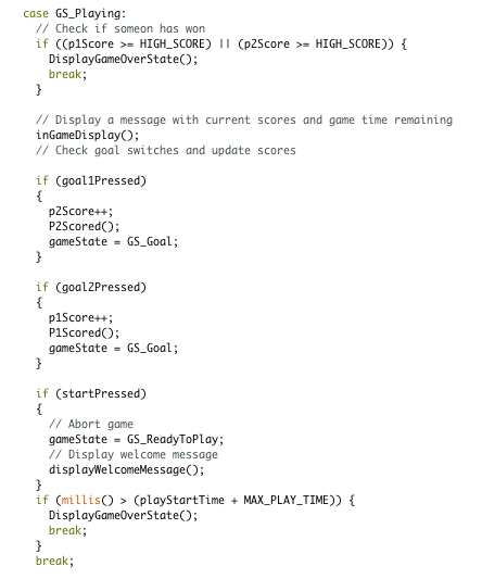
In play mode, the programme is checking;
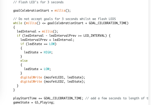
The final section of importance is the goal celebration. I want to flash the LED's and show a LCD message. I didn't want to simply use the delay function as this would send every function to sleep which is not desirable. In order to achieve this, I used the millis() timing function.
With this function, I start counting with millis() and whilst an interval is not reached, then enter the while statement. There is a nested if statement now, which has a very short interval of 200mS. If this interval is reached, change the LED state from HIGH to LOW and vice versa. I use this time of 3 seconds to flash the LEDs and not read any new goals. After the celebration is reached, then exit the while loop and add the celebration time to the game counter (otherwise 3 seconds would be lost)
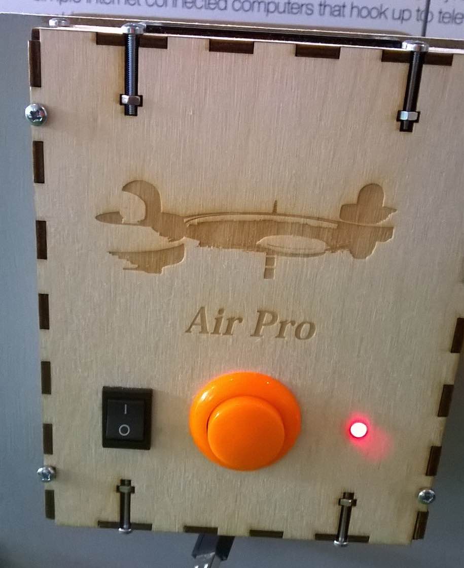
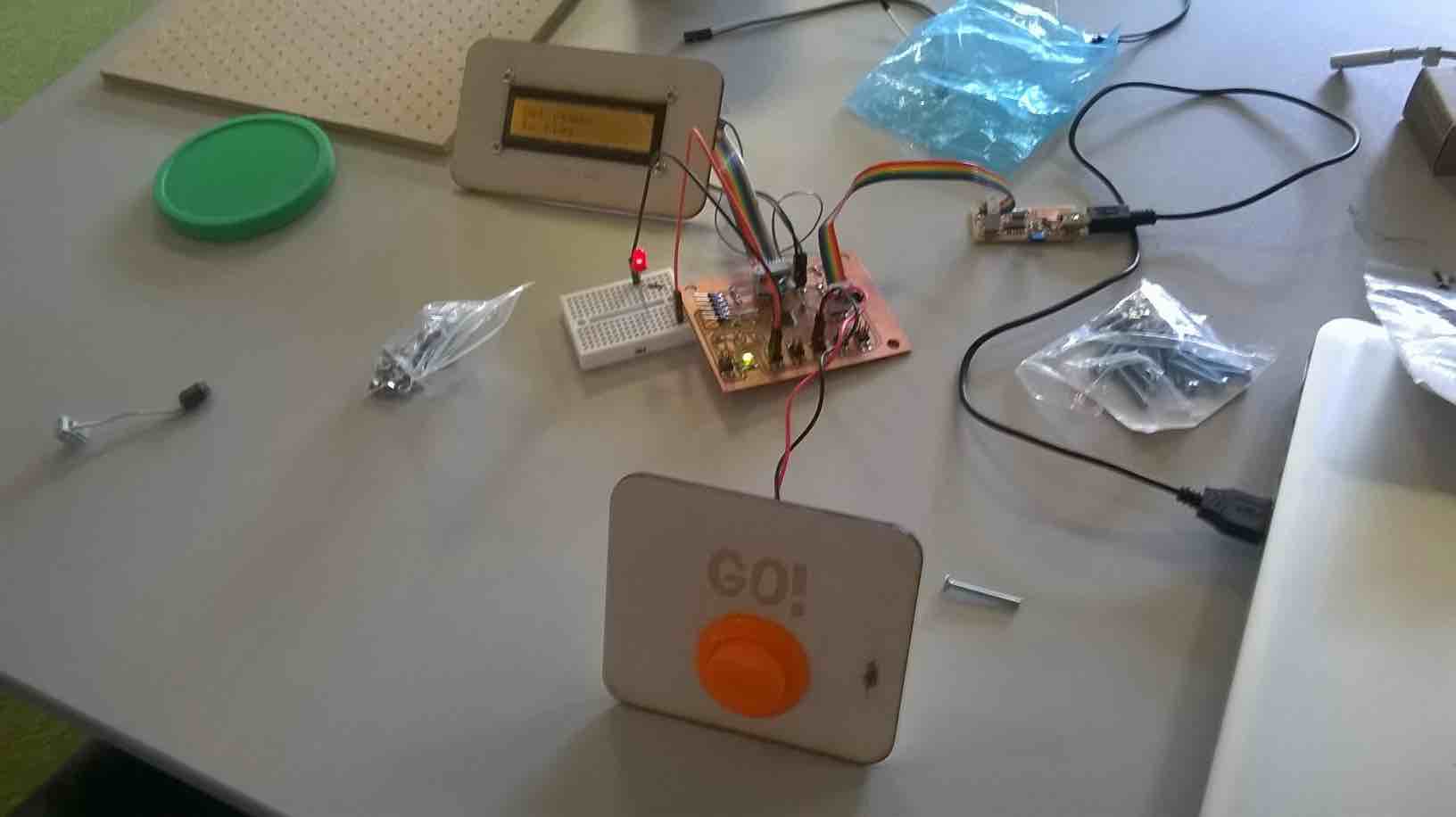
As soon as I had the basic circuits made, I wanted to protect them from being knocked, as every so often some of my wires were fraying and disconnecting. I decided to make a controller box which housed the;
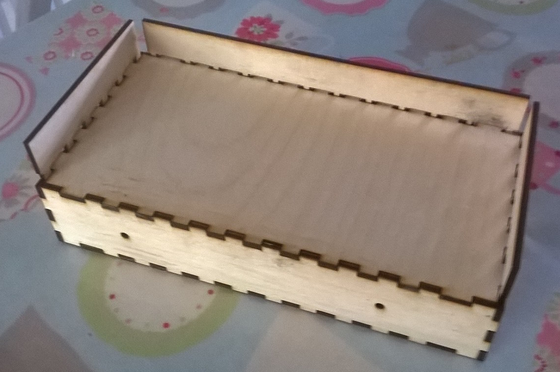
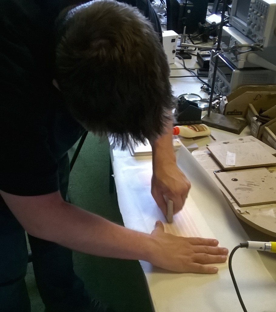
My first 'spiral development' was to create vector layouts of all the parts that need to included on the box. I used scrap wood for testing this as you can see in the image below. This put less stress on all my circuits straightaway but I decided to change my LCD display to one with header pins which I could connect female to female connector pins to directly. This took a lot of pressure off the LCD but there is added weight on the circuit board, so I decided to work quickly to create a solid enclosure.
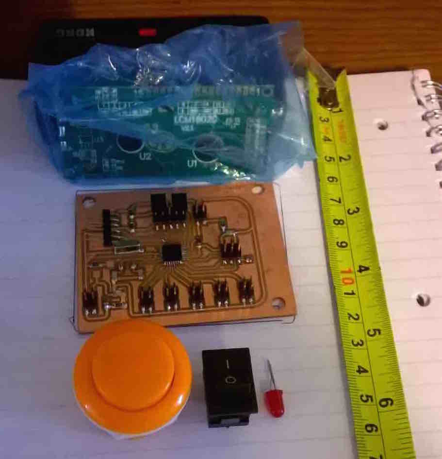
The image to the right was me trying to work out what dimensions I would require for the box. I need to give enough room for all the components but not too much so the box is bulky. The great thing about this prototyping method is that I can knock out another one within an hour if the size is wrong.
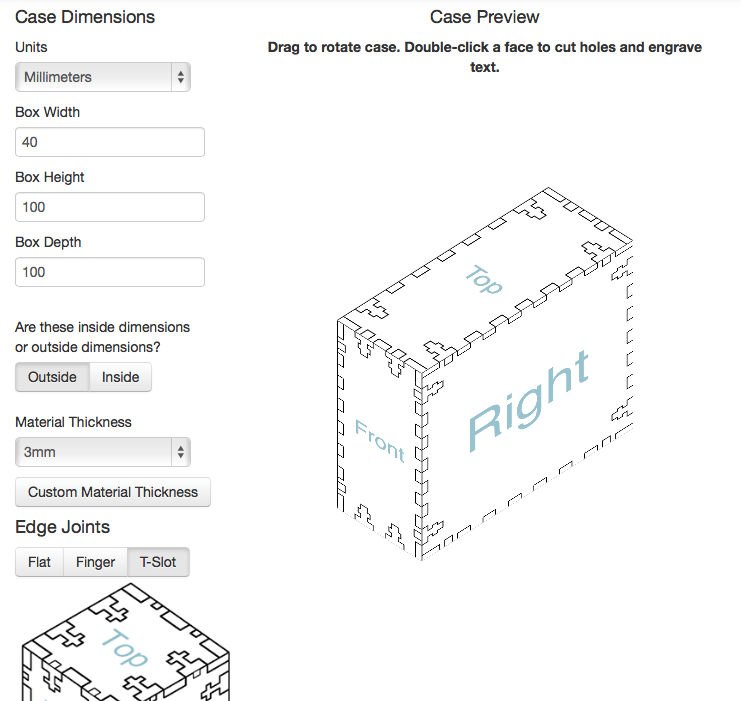
I wanted to make a box that would look good but also be easy to assemble. In Manchester, we have been using an extension in Inkscape called 'tabbed box maker'. There are a couple of reasons why I don't particuarly like this tool including not being able to see a 3D view of what I am making and a lack of fastening options. In light of this I decided to use an online tool called MakerCase which allows you to create a box of your dimensions and add different fastenings
With the project end date looming (and I did want to show Neil my working design), I set about doing the large enclosure.
The air bed was quite an ordeal yet it was the simplest part to shopbot. With all the holes that it had to do, it said the job would take 2 hours... it lied... it took 5. As a result, we had to stop the job part of the way through inorder to continue it the next day. Knowing at what point in the job it stopped, we took note of the G-Code and where it was. When we came back the next day, we simply deleted the G-Code before this point in the job, and carried it on. Unfortunately the drill went crashing into the bed because it began plunging too early. This is because we had deleted the part of the code which allowed the tool to locate the hole. Lesson learnt, but there is no time to go back and do it again!
As there were 3 other people wanting to use the Shopbot, I decided to take advantage and head over to Ellesmere Port to finish off the rest because the Shopbot was free. It took another 5 hours to mill the rest of the sheets but there were not issues to report.
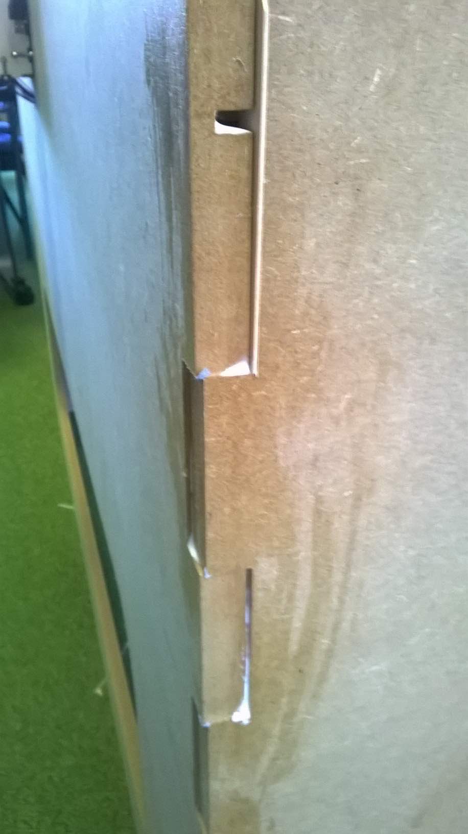
So I now had all the sheets, I was ready to assemble it all. This took a long time! Due to me not putting any tolerances into the cut lines, so the parts did not slot together very well. I also forgot to put any dog bone corners into my design meaning I had to do a lot of sanding to get the right slot size.
In the end, I had to put all the sheets back onto the shopbot and mill away 1mm from the airbed slot inorder for it to fit. After this I used corner joints to hold it together securely. This is something I would really improve on next time.
There is a sign in fab lab Manchester 'Glue is a sign of failure' NG. I never really took too much notice of this and thought it was a bit silly as glue is in nature as well. But then I found myself using a lot of wood glue inorder to stop my project from moving too much and I understood the point. This was a design flaw which I would go back and change the enclosure to prevent this from happening again
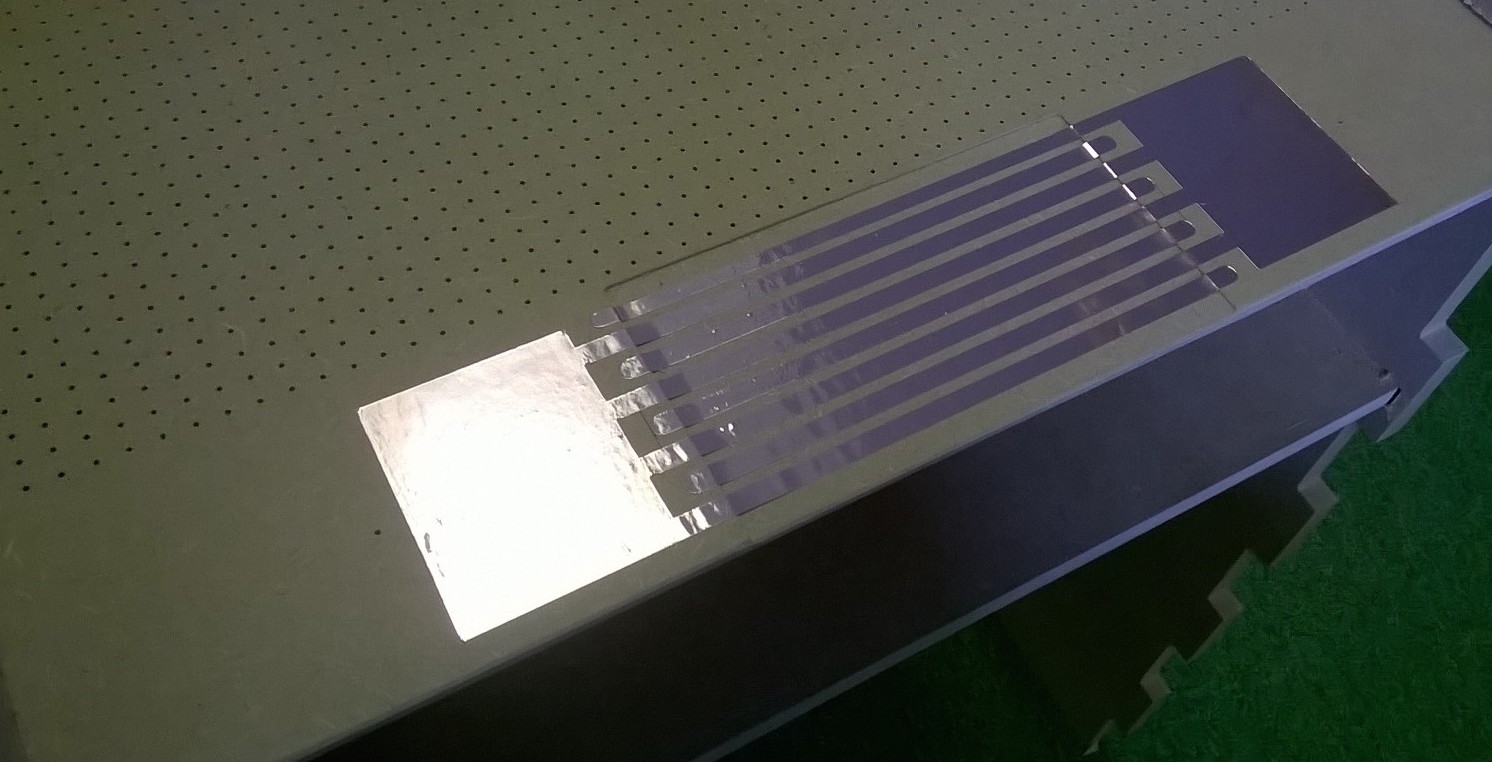
Finally, I laid my copper zones onto each players end. This took patience but I was very happy with the resulting look. The connections were hidden by corner joints that were glued down (another sticky point!)
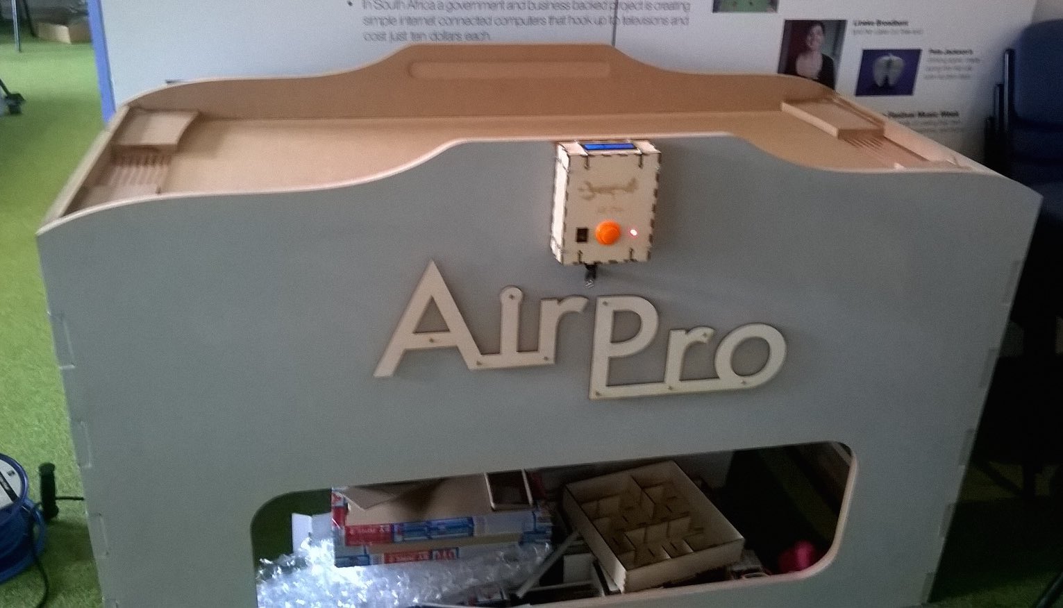
I utilised many of the Fab Lab processes inoder to create an Air Hockey table including:
It is a fully working Air Hockey table that when turned on; turns on the fans and counts the goals scored and the games won by the players. The air bed fully works and really helps the puck to glide.
In general I am very happy with the project conclusion especially as the air system works and it detects the goals! Regarding, notes for improving version 2, is best answered by individually looking at each part briefly
There were a couple of issues with the board including;
As described above, when I turned on the MOSFET boards for the first time, there was blue smoke from one of the MOSFETS. I put this down to issues with my design including a lack of back EMF protection (large diode), but the main reason being the gate pin was not pulled up or down to stop it floating. The final change I would make is to add some type of thermal protection, though it is in a breezy area it would be better with a heat sync or some sorts
I can greatly improve on this aspect on the project. I would look at adding tolerances to the design so it easily fits together. I would also look at how to create an enclosure that doesn't show the tabbed slots on the sides (hidden joints). Finally I would look at a system that incorporates the goal detection system into the main enclosure (such as a shoot).
Though the system works in most instances, the copper is already getting damaged and if the puck only just goes over the edge, no goal is detected. Next time, I will look at a better solution to the goal detection.
From this project, I have learnt many elements of product development. One of the most important lessons I have learnt is time management which is crucial for a successful project ending. I also learnt to use spiral development to work on individual elements. This allowed me to test my design ideas quickly (usually using scraps of material or sample code). Finally I extended my knowledge on almost all processes used in FabLab, making it easier for me to work on future ideas in confidence.
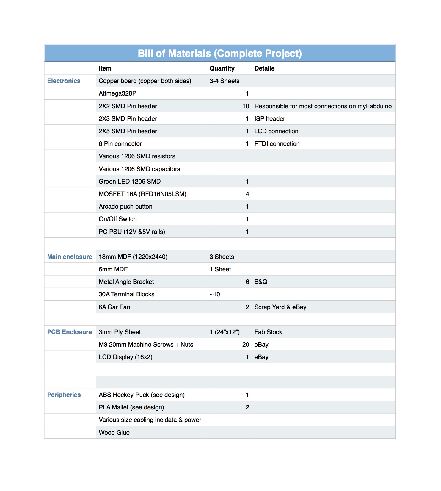
All design files are below and here is the bill of materials.
AirPro Enclosure (Solidworks) - Keep the equations file in the folder in order for it to work
My Fabduino (also includes an updated version with better spacing)
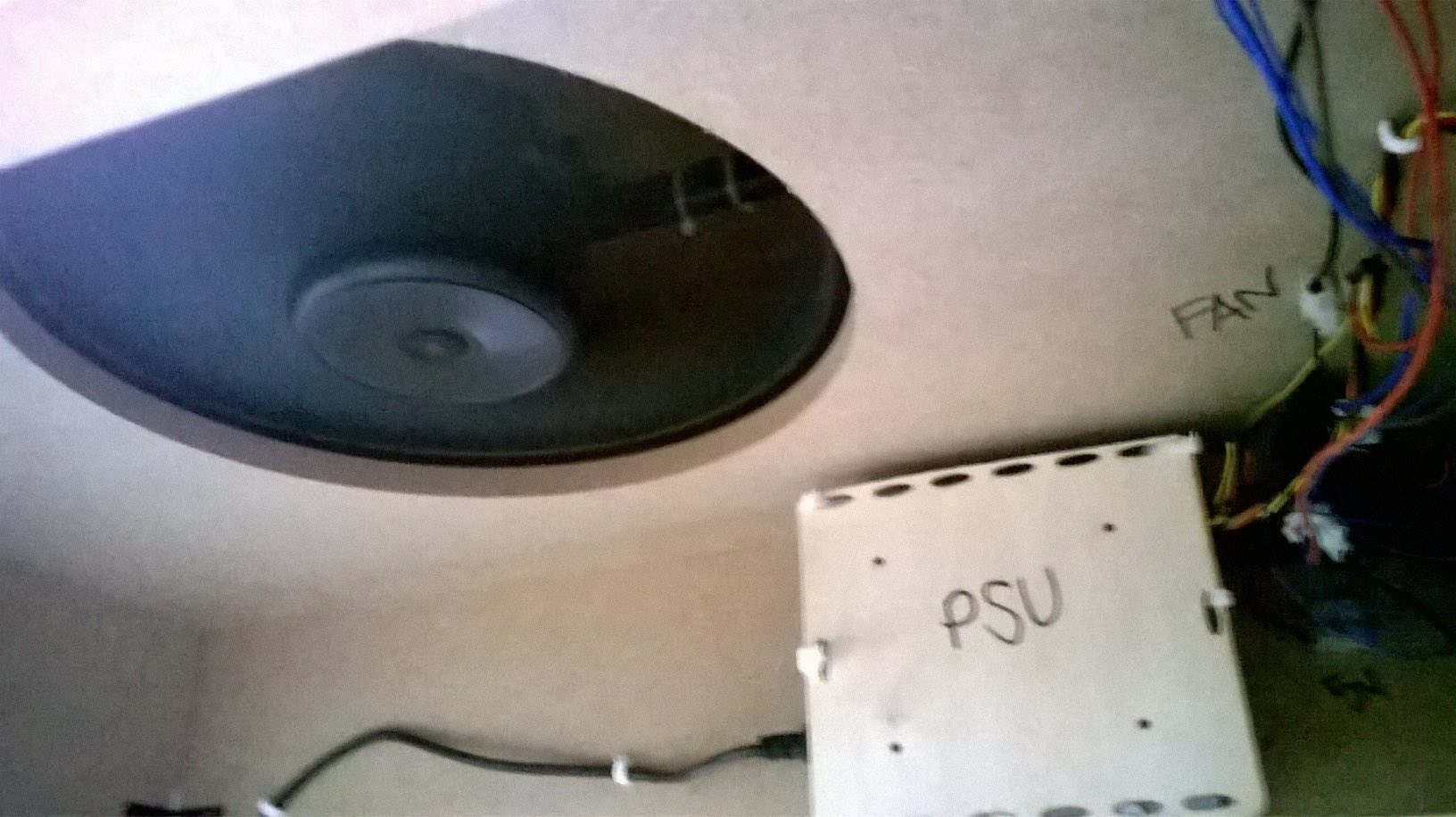
PC Power Supply Backing (Use zip ties to hold it on side of enclosure)
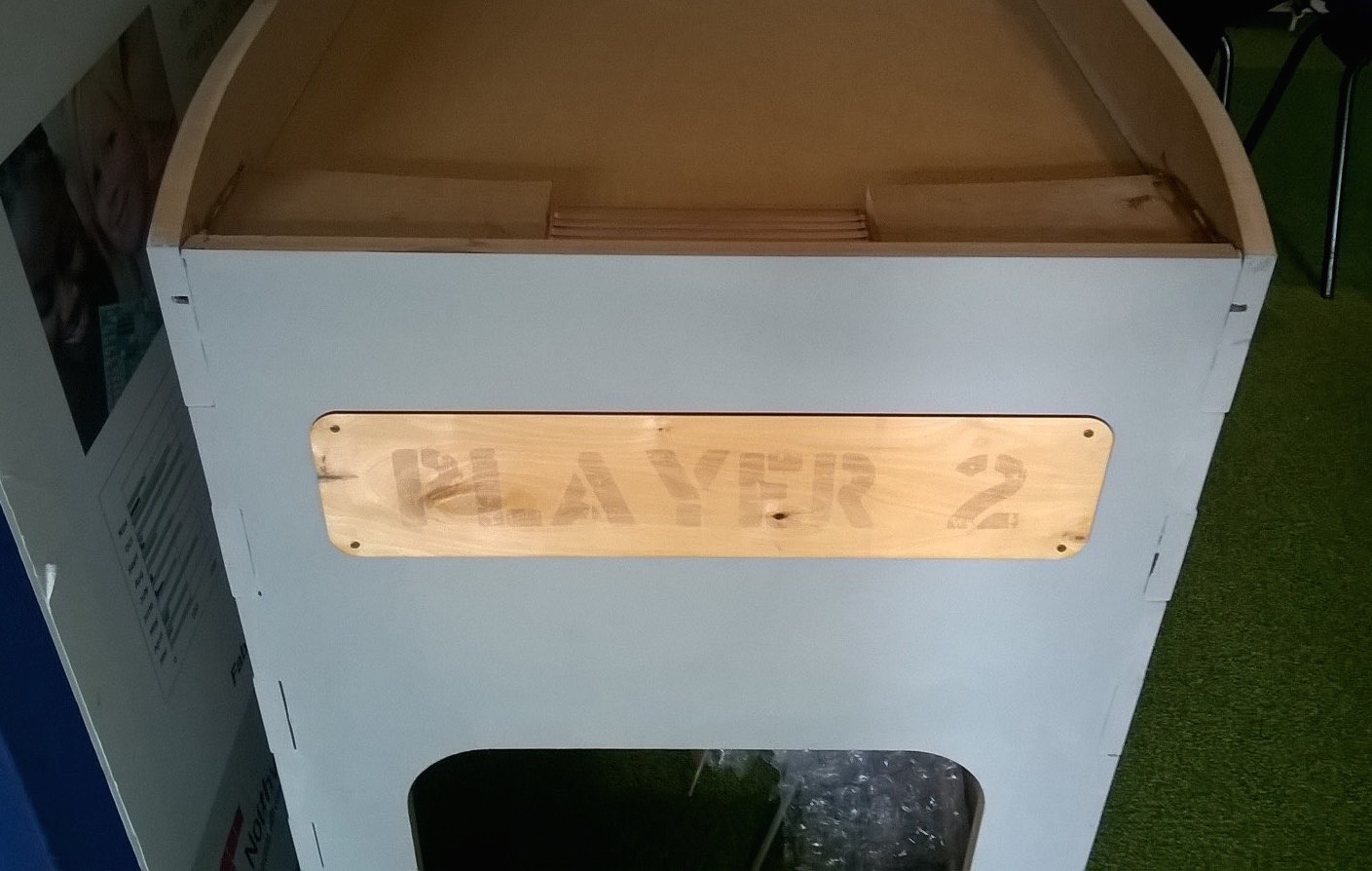
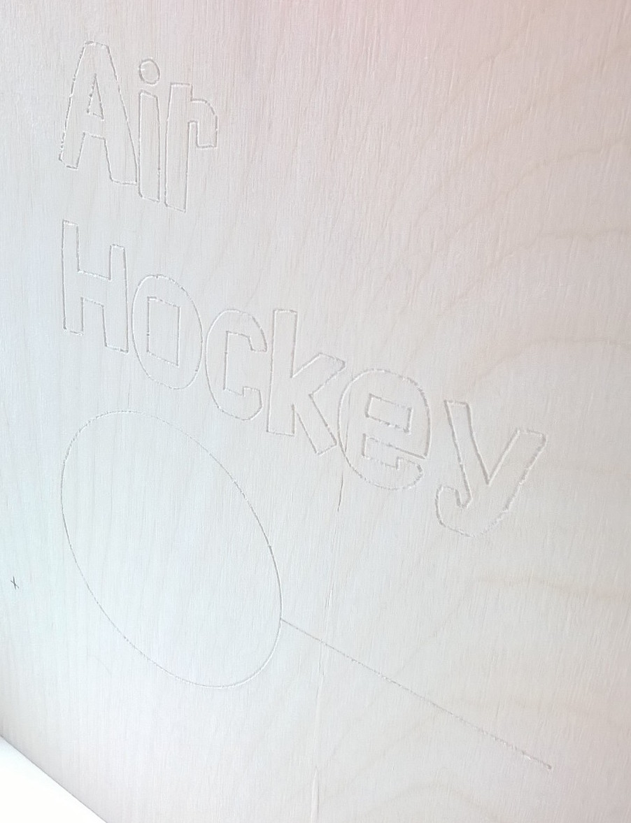
Laser Cut Signs - Player 1 and Player 2 signs and AirPro sign
Shopbot Machine Code. All files are numbered in order and have details of toolbit and speed.