19th February - Fab Ellesmere Port
After watching Neil's lecture the day before, I was keen just to get experience with creating my own PCB and to solder to it. I already have previous experience of soldering as this was my previous job, creating specialist circuit boards. I was more interested in seeing the process primarily from an experienced user before reading the instructions (I learn better from example than text).
I found the process fairly simple to perform and got valuable guidance from Dave and Tony at FL Ellesmere Port regarding good practices. Here is the procedure that I carried out:
- Through Ubuntu, I logged in to Fab Modules through the terminal with 'Sudo Fab'
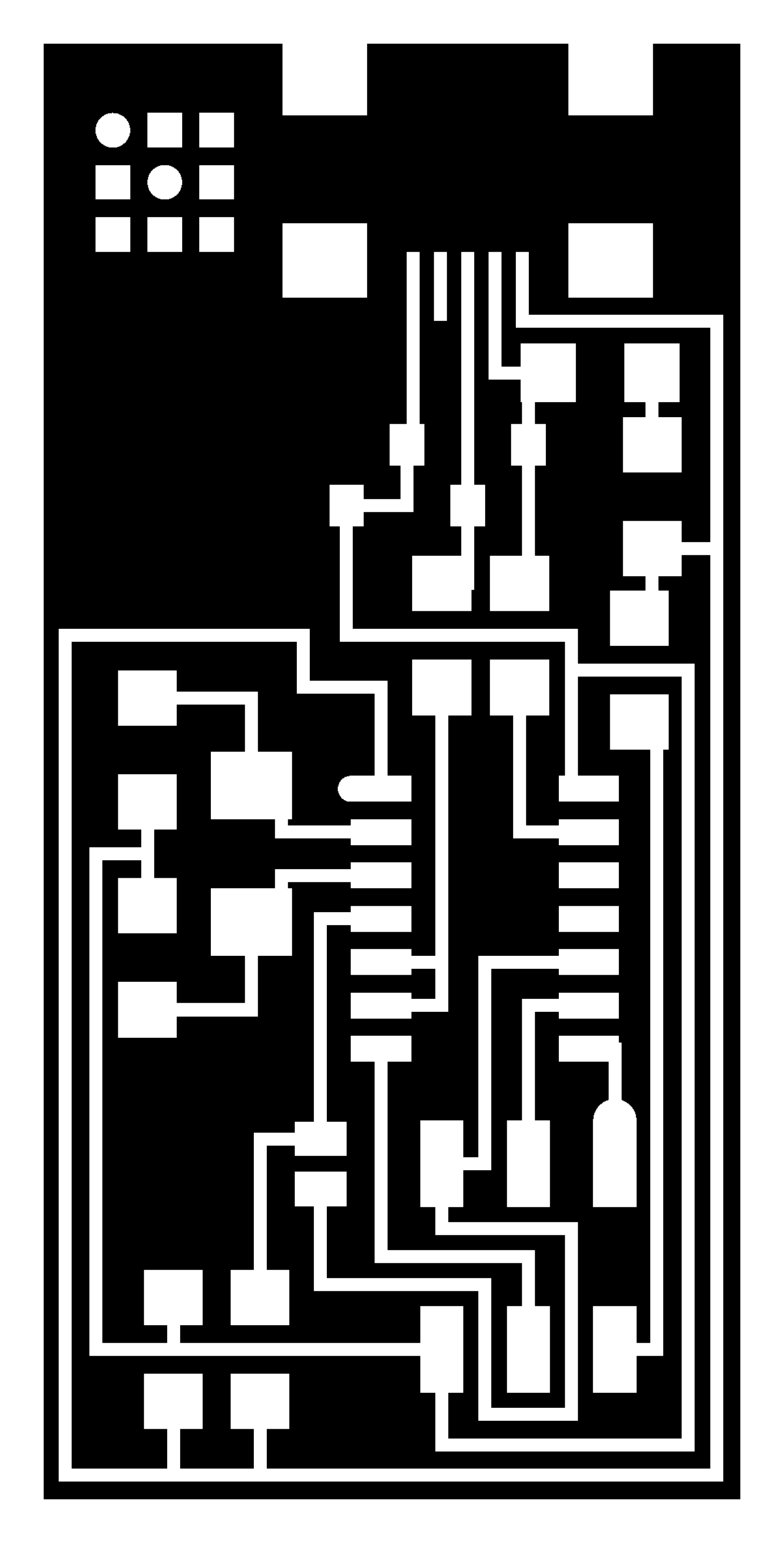
- I Downloaded the traces.png and interior.png files for the Fab ISP, I used the one with the crystal, not resonator
- Initially I laid the copper board in the wrong orientation which was slightly frustrating because I had to take it off and lay it down again, which is not preferable!
- I then changed the bit to the 0.04mm bit which is used to create the trace lines. I firstly did a pass of 1 to ease into the board, and then went back and did all 4 passes.
- After this, I changed the bit to the larger diameter and proceeded to cut out the board using the Fab Modules drop down option. The important thing to remember is that you need to create a border around your circuit which the circuit will follow.
- Once this was done, I removed the board and cleaned it using a metal scrubbing brush and sandpaper as the finish was quite rough
One the circuit was cleaned up, I proceed to solder on the components (smallest first) until it was complete. There are two locations on this board with temporary connections which will be removed later on after programming. Programming the board was not my concern today but I went through the process with Dr Dave Armson which showed there was a fault with my board, which was with the USB connectors, these are usually quite challenging to get right straightaway. This is why I prefer using solder paste to soldering because the footprint for the usb connector is very small and soldering can overheat the area. I plan to try and solder all of them together and then mop away the excess, as per Neil's recommendations.
23rd February - Fab Lab Manchester
This was a morning of going over the process again, but it was very valuable. I learnt key skills such as ensuring the sticky tape is perfectly flat to gain a better finish, and if the board is slightly wonky - start again rather than allowing it to finish and then going deeper into the board. Here is the process I used for changing the bit:
- Push the bit in until you only see the blue part sticking out (this ensures the Z axis can't smack the delicate bit into the board)
- Only tighten one grub screw whilst you are positioning in place
- (Tool Down Button) until there is a small gap in the rail (so the bit has room to go down)
- Position in X and Y Plane where you want it
- Supporting the bit with a finger or thumb, lower the bit down to the board.
- Apply a slight bit of pressure downwards and then tighten both grub screws until snug and tight. Don't over tighten.
Before we milled the boards, we changed the drill bits to brand new ones, which was a real comparison with the one I made in Ellesmere Port which needed a bit of final polishing. Here are a few pictures of the process with relevant comments:
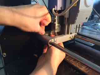
This is a delicate procedure to ensure you don't drop the bit onto the board or overtighten the bit which damages the thread or grub screws
This is fiddly as you need to make sure that the tape does not get wrinkled, this will affect the final milling if so.
Ensuring that the copper sheet does not move is imperative. Pressure is applied in strokes to remove any air pockets.
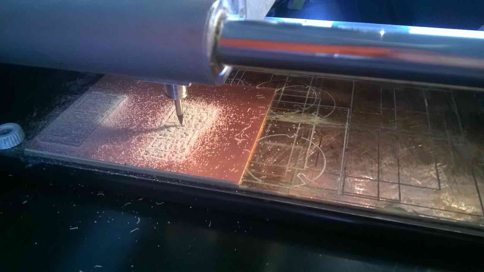
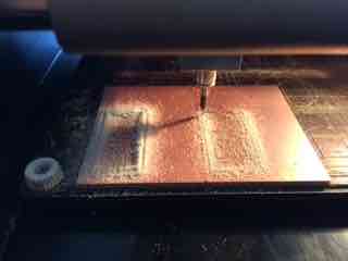
Once all settings are calibrated in the software (Fab Modules) and the X,Y and Z is set, we move on to the milling, first is the traces. Me and my colleague Kasper were feeling lazy to do individual jobs, so we butted our copper pieces together and just relied on the X and Y being changed between the two. Not lazy, just thinking smart.
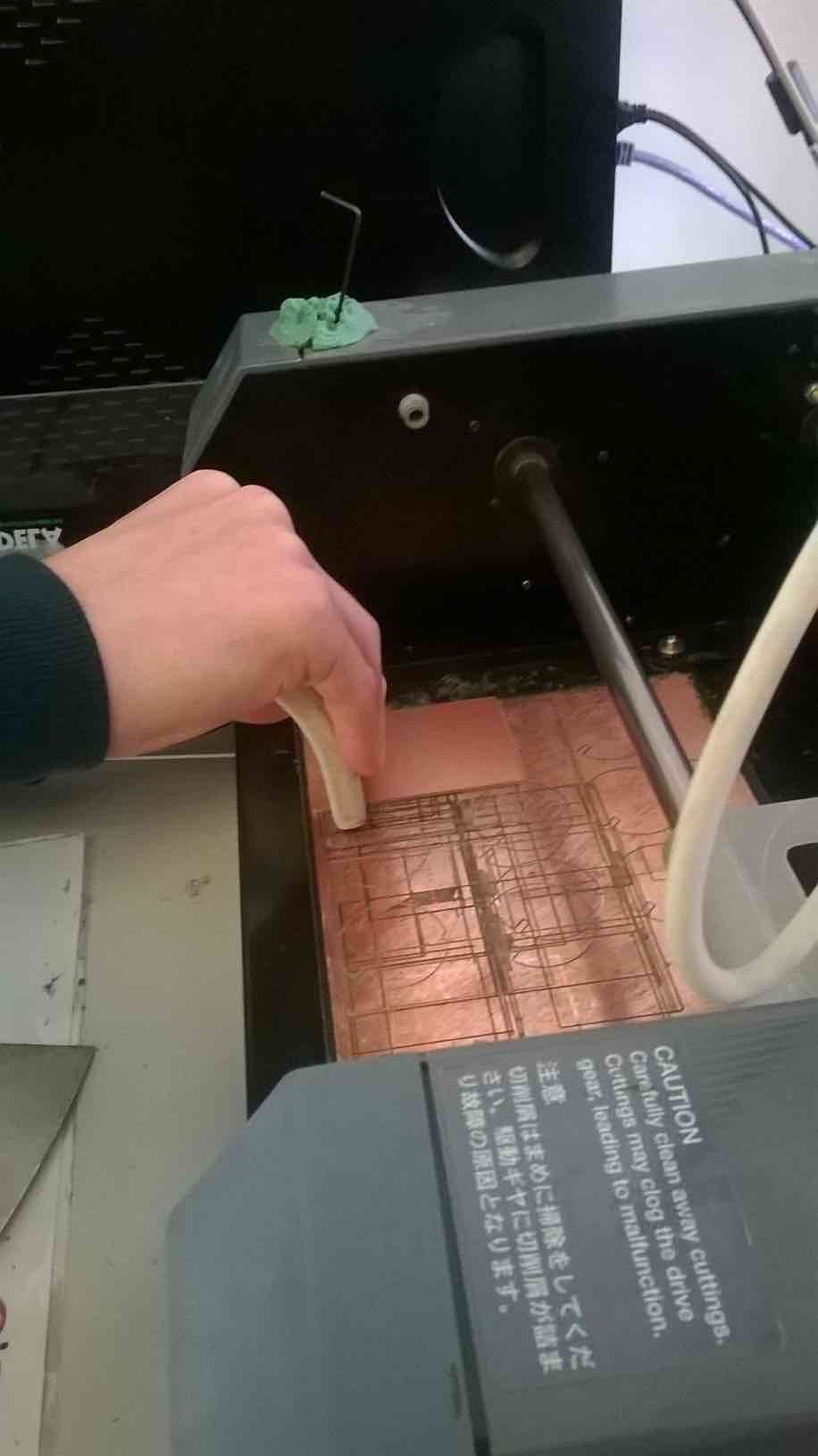
This is the outside of the PCB being cut out with the larger bit.
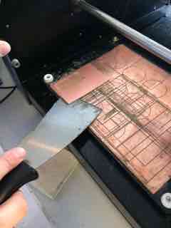
A bit hard to prise off, because it is quite easy to snap the copper. Allowing the scraper to do its job is the best advice, don't rush it.
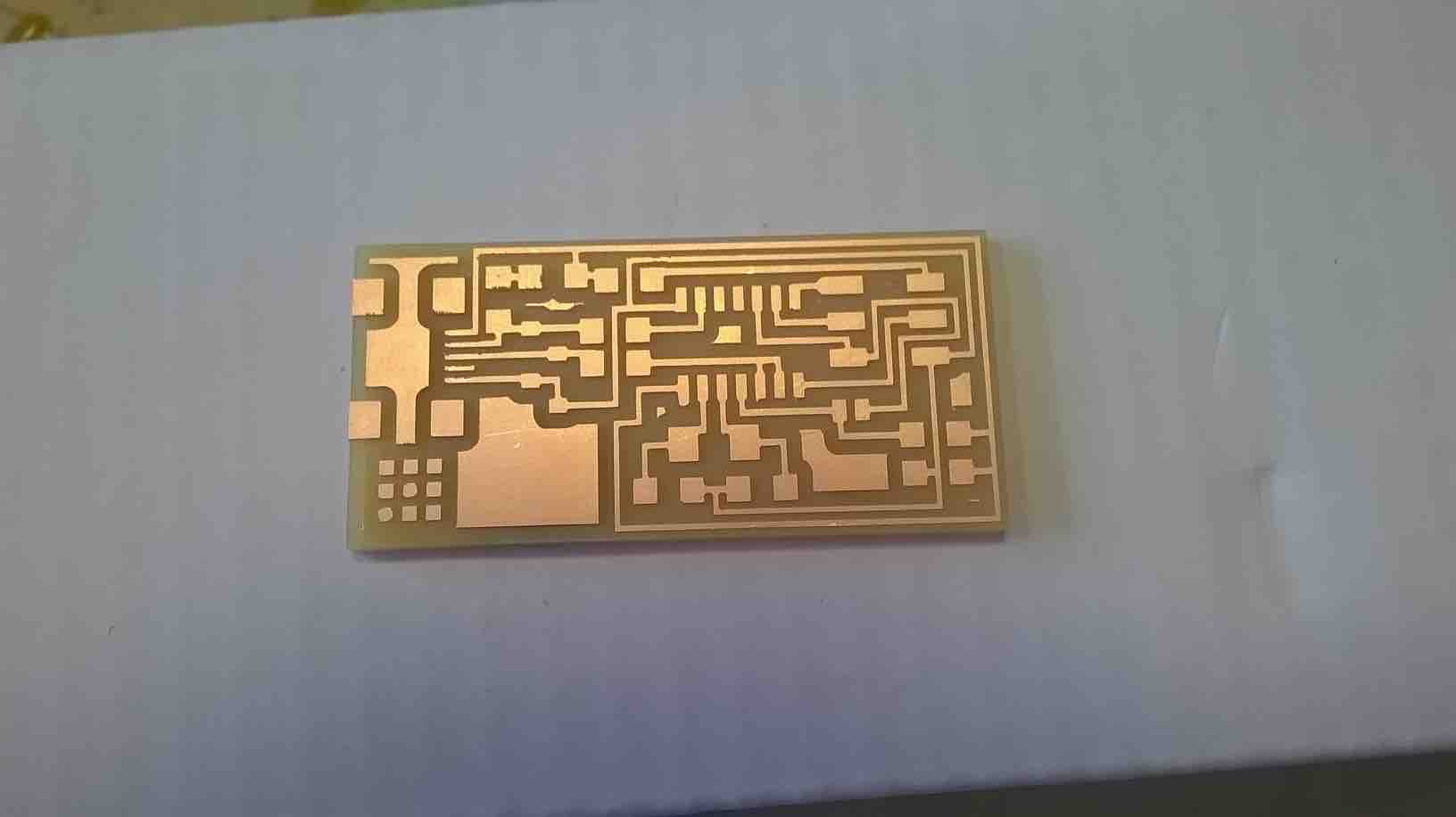
This picture shows you the effectiveness of a brand new bit being used. This is almost how it came out of the milling machine, wonderful.
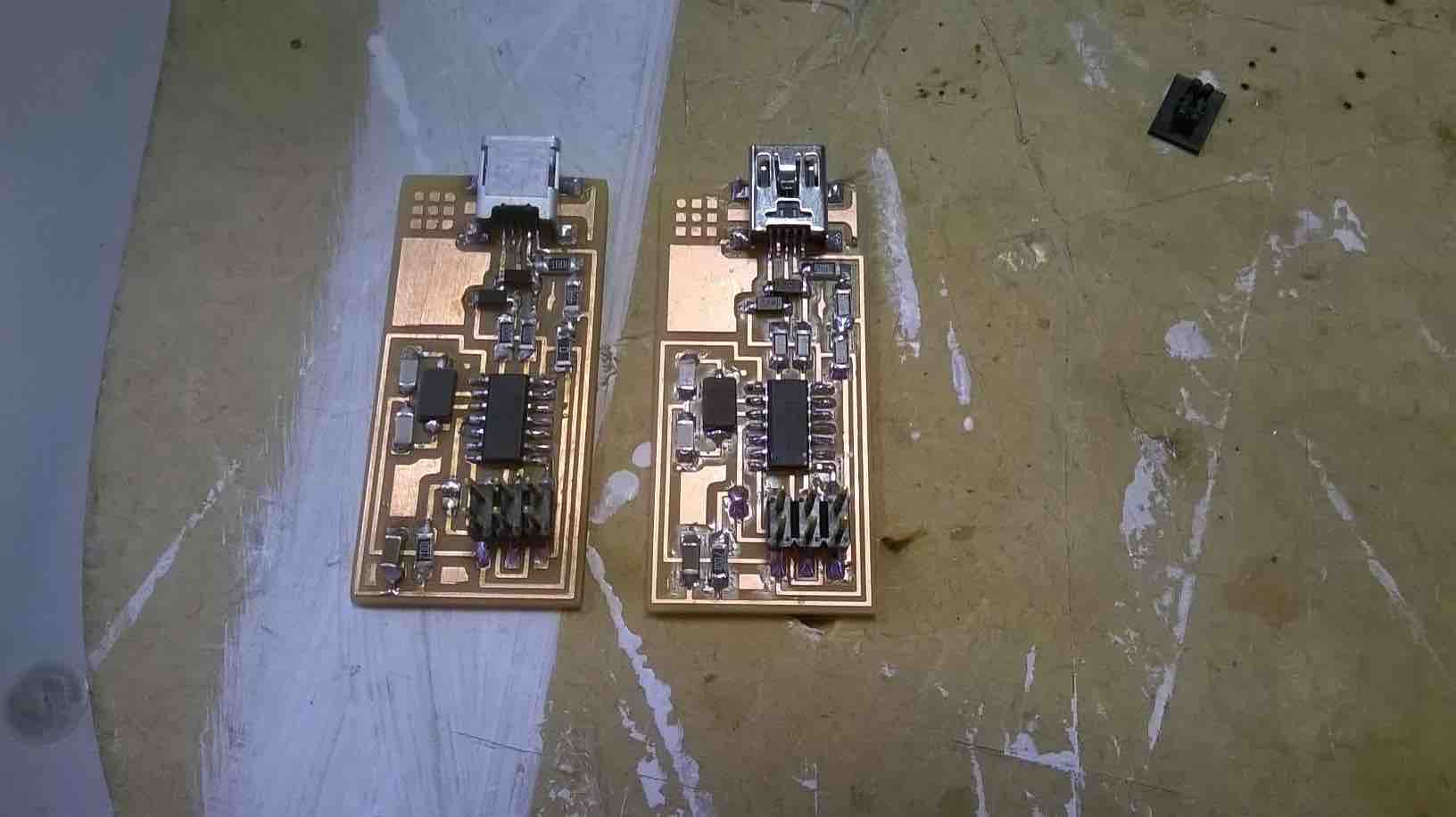
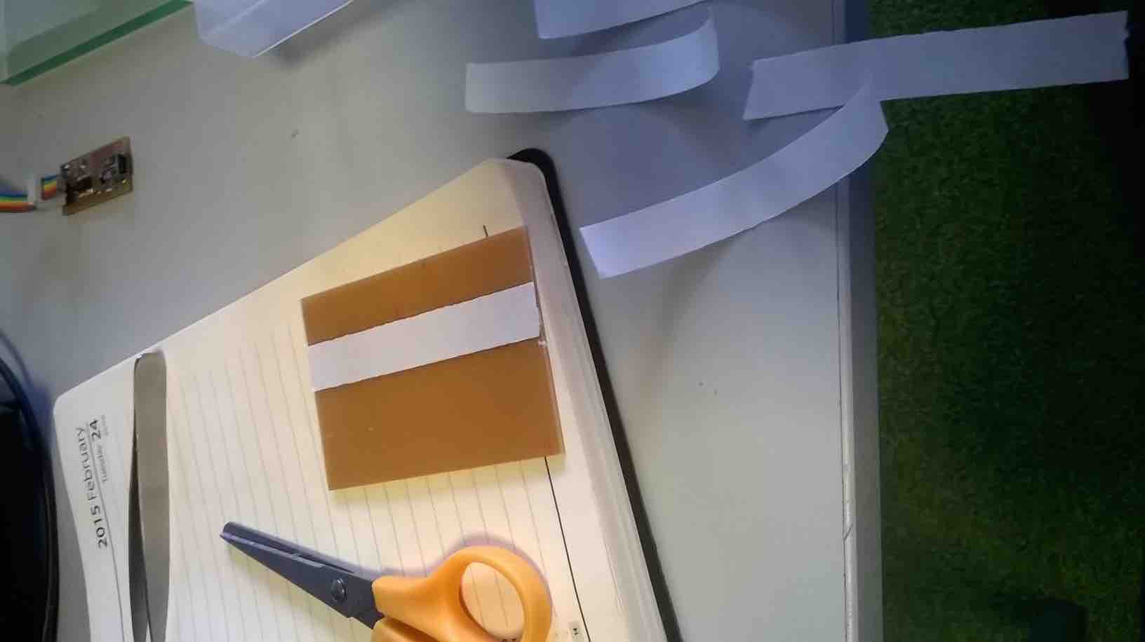
This is a comparison between the PCB I made at FabLab Ellesmere Port (left) and the one I made in Manchester (right). I blame the circuit on the left for being discoloured for two reasons, one I did not wash the circuit board after milling it and two, I did use a soldering station with adjustable temperature which doesn't overheat the board too much.
Programming the Device
This was a farily simple process (though I will not pretend to know what is happening when I type the commands into Mac Terminal) In order to programme the chip I used the following website from Fab AS200. The only thing I found difficult was the ISP headers can be attached in two directions, so it is easy to accidentaly attach it the wrong way round. which could cause problems. Below is an iframe of the other website.
Look Neil, no glue!
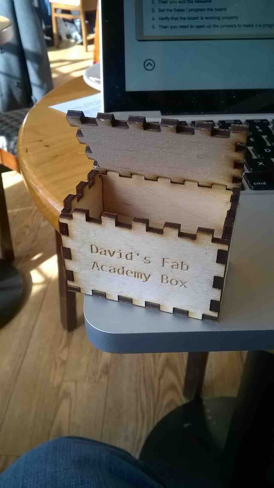
I could't just let my prized circuit bang about in my bag, so I used the tabbed box maker extension in Inkscape to create a small box
