After the lecture, I set about thinking what I could design and then 3D print. I had ideas of creating objects wrapped around a sphere in Solidworks (then the sphere being removed) but I thought this might be a bit too advanced for my Solidworks skills. I must add that I have access to my own 3D printer by Robox (a UK 3D printer), so I will spend some of my time using this whilst I am not at FabLab, I have not had chance to really road test it with my own designs, I will report back with the results. Despite this week being dedicated to the actual 3D printing of an object, I decided to invest some time in another software, Blender.
I decided to undergo a short course in Blender via the Udemy tutorial site. I have done tutorials with Udemy (such as html and css) to further improve my skills, I recommend to anyone to look for suitable courses as often they are very cheap and do help you break into a software. I now don't feel dread when looking at blender controls, but I don't think I am at the stage of some who 3D design loafs of bread in blender for games (seriously YouTube it, it's great!). Keep reading for my review on Blender as a 3D design tool.
When you first load Blender you are presented with a cube in the centre axis of the screen, this is the default startup file. Through learning Blender, I realise just how much of the software is customisable. In short Blender has two modes, object mode and edit mode. Once you have inserted a shape into the centre, it is then upto the user to 'carve away' at the material until you have the ideal shape. This can be compared to famous sculptors who see the shape in the marble and chip away material to release it (without the risk of breathing in marble dust of course).
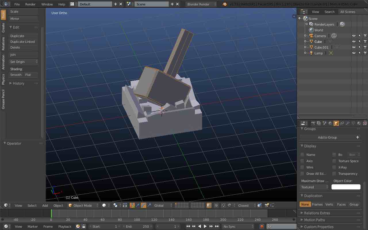
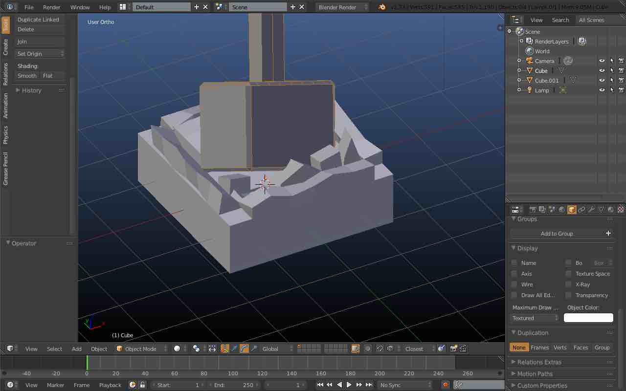
I created two objects in Blender, the first was my initial steps into 3D modelling with slight manipulation of an object to see the effect in a 3D print, but also I wanted to see the process of exporting as an .stl. I have to say that this was my first failure with Blender as if you don't select the object on screen, it will not export as an .stl file properly as the 3D printer could not ascertain the objects dimensions (see image below). This led me to asking the Fab mailing list for help so I am grateful for Colten Jackson and Demetrius Comes for assisting with this issue.
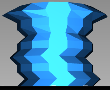
The first object that I created was a square shape broken down into multiple faces, which I manipulated slightly to see how it came out on the 3D printer, unfortunately I did not save the Blender file but the .stl can be found at the bottom of the page with all my other files.
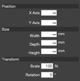
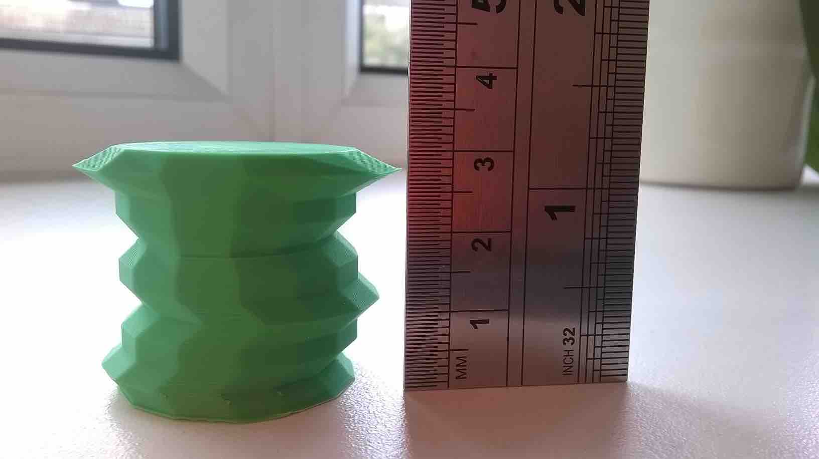
When you begin working with Blender, it has no obvious dimensions type attached to it. It is possible to incorporate a measurement (i.e imperial or metric) into your objects but I find that Blender isn't really suited to parametric designs because primarily it is a graphics tool allowing you to create awesome objects with little difficulty. If I wanted to keep measurements on all my edges, I would use Solidworks. When you import the .stl into your 3D printer software, it will need resizing. In my software Automaker, I can change the height, width, depth and scale to change the dimensions of my object. Below you can see an image of my first design which was printed with a height of 30mm, which shows the accuracy when printed.
I was very happy with the results of the first print, both from a design point of view and from a print as well. A guide to how to 3D print with Robox is below, which shows you what you need to do to get good results. Lessons - The angles on this design were sufficient for the 3D printer.
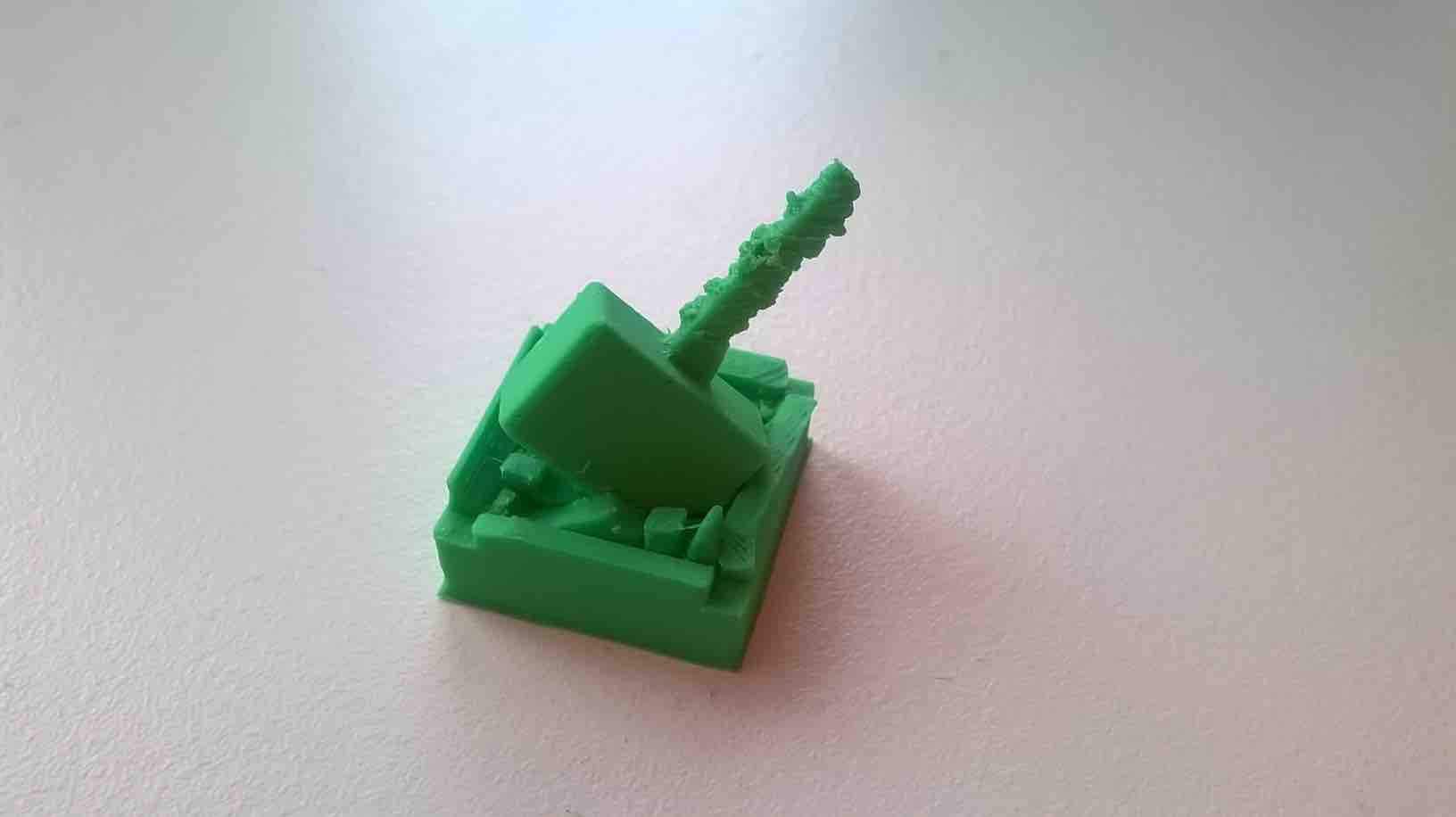
After this print, I wanted to do a more complicated design which would test other aspects of the design such as extreme angles, filleting and nonflat levels. I had an idea in my head which I believed I could realise in Blender, Mjolnir! I won't go into detail on how I created the object but you can see the finished 2.5cm height print below.
I set my 3D printer to finer resolution and also set the speed to 0.5 to try and ensure a good print. As you can see the print generally came out very well except the handle which came out all bobbly. I put this down to a difficult angle for the printer to handle and also a too small surface area for it to print well. I am going to say this has been a success because I have tested the limitations of the printer and seen its shortcomings. I now plan to retest the part but by trying the auto support feature in Automaker and also just making the ground more uneven for better effect
After creating the hammer shape, I wanted to see what the Robox community thought of my design. I got some advice from another user who said that the two meshes were not 'unionised' meaning they are not one. I tried to union the two in blender, but it would not let me due to an error. I then ran the model in 'Netfabb' for issues, there were some but I plan to use this software more later on when 3D scanning.
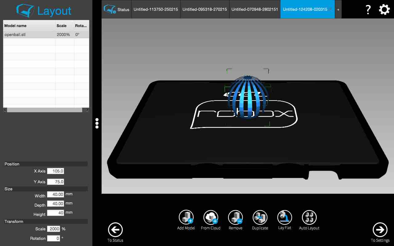
I then tried to 3D print the first object I really was able to create in Blender which is a sphere with individual sides removed. This proved to be unsuccesful attempt with the printing as it failed to print past the base of the body, so it failed when trying to do the sides. I need to look into this further, I think it might be because Blender is mainly a gaming animation designer so the sides are very thin and the printer doesn't like this.
A guide to the Robox Printer and Automaker
Robox is a 3D printer from CEL based in Bristol, England. They had a succesful Kickstarter campaign which gave them the funds to begin maunfacturing their 3D printer. Here is a brief rundown on the features of the Robox printer;
Dual nozzle head capable of doing fine detail with the smaller nozzle whilst using the bigger nozzle to do infill, which speeds up the print
Enclosed space for allowing more control of atmospheric temperature and less chance of drafts causing issues (though it can happen still)
Special material heatbed which gets sticky when heated up (no hairspray required!)
Automated bed levelling programme
Dedicated suite for Robox called Automaker
Level detail upto 20 microns)
Automated reel service which knows the type of material going through based on an EEPROM chip in the reel container (though other brands can be used)
The automaker software is very easy to use, please see my video for a more visual look at the software
A 3D Printed Buckle Design
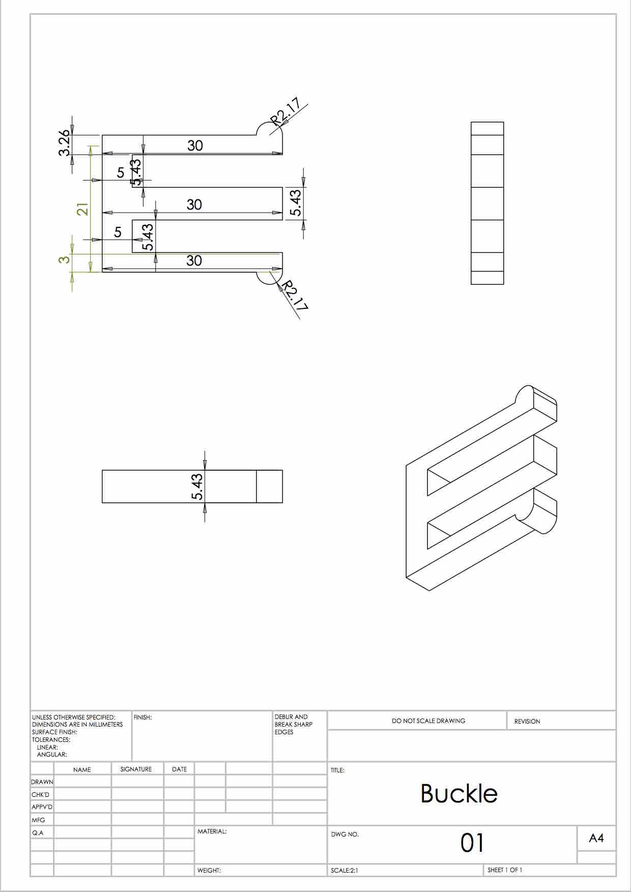
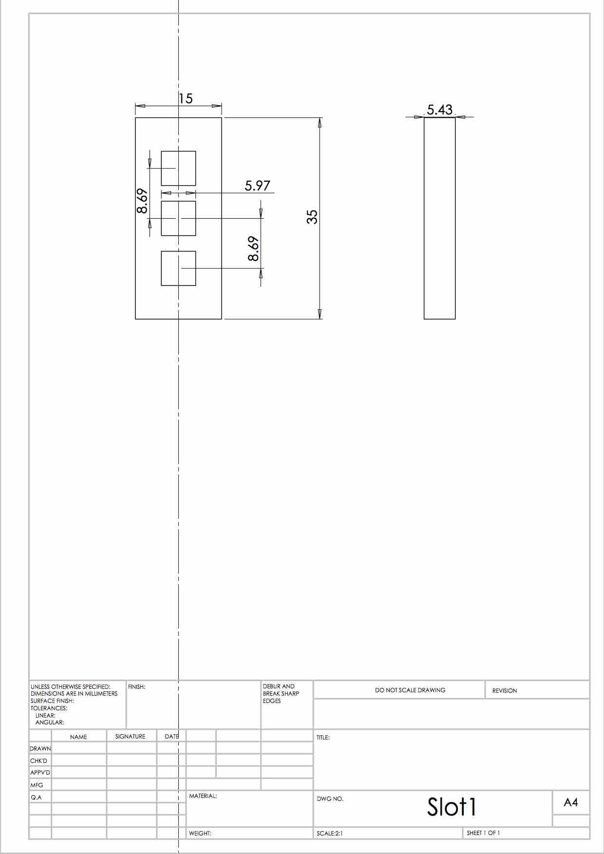
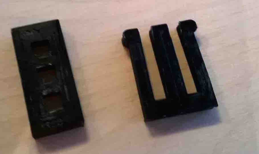
I wanted to test kerf theory with my 3D printer, I designed a simple buckle and slot design in Solidworks which had matching pin and slot dimensions (5mm x 5mm - See drawing below for more detail.). These printed really well and I was excited to try their tolerances when slotted together. Let's just say that the fitting was very tight and needed some investigation.
This is a dimensional drawing of the peg and slot. Note the dimensions of the pegs and holes.
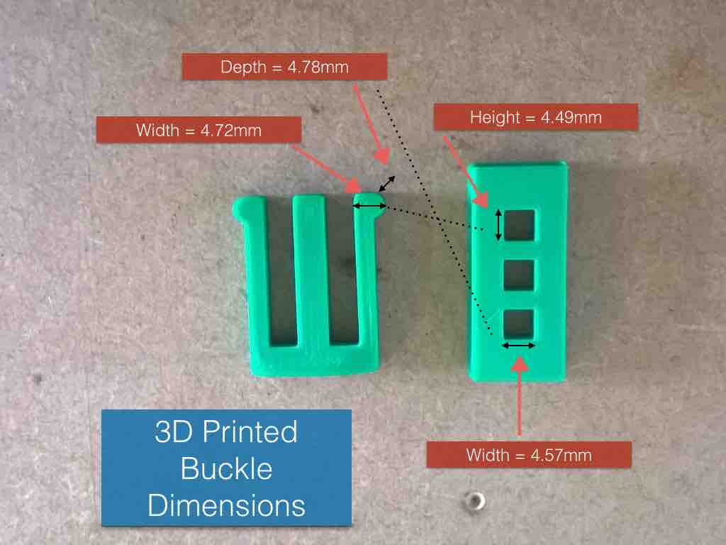
This shows just about why I was having trouble slotting the two together. None of the sides came close to 5mm (but at least they all have fallen short (creating relativity).On one plane, the peg has a dimension of 4.78mm and a hole of 4.57mm, this leaves a 'tiny' clearance on each side of 0.105mm which makes it possible to fit but the more surface going through stiffens it. The other side has a similar gap of 0.115mm. I am now going to go back and adjust my measurements to attempt a 5mm piece. With the next model I will;
Amend the holes to be .5mm wider to accomodate the peg
Also incorporate an overall 8.6% increase in the hole dimensions to accomodate for the shrinkage in ABS
Also increase the overall peg dimensions by 8.6% to take into account the same loss
leave the overall dimension of the component (though this is out by 2.1%) until the holes are more accurate.
There is the option to amend the overall size in Automaker (as well as other softwares) to adjust for the ABS issue, but the design I have done incorporates holes and outside edges which don't shrink in correlation with each other. It is best to amend the drawing rather than the .stl so I will try and create a couple of variables in Solidworks to allow for that change.
I went into Solidworks and created an external .txt file that created global variables for my Solidworks parts. I then added this global variable for all my Solidworks parts. This made it very easy to do parametric design (I will be doing this from now on!) in Solidworks, unfortunately the 3D printed part I did at FabLab was with a different 3D printer and a different material, so this needs more work to create a good fit.
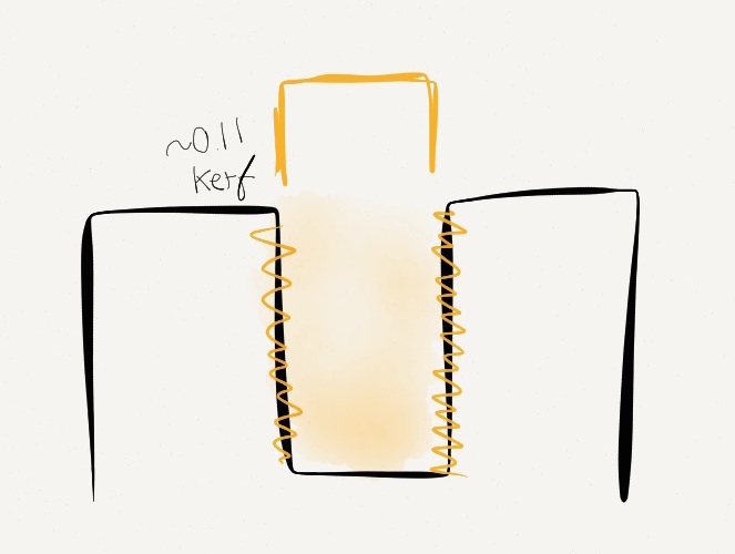
The 3D printer doesn't print vertically in a solid piece. Moreover it is similar to a cake maker who works with layers, and these layers have a filleting edge at the edge of the material. This leaves a slight ruffled edge (which I have overexagarated for clarity) to the model. I see there being a positive kerf with 3D printing, as it deposits a inner edge that was previously not there on the design.
123D Catch App
I have played with this app several times. I found at first I could get some decent results but when I came to FabLab Mcr, I struggled to get anything worth keeping so I am going to keep trying to see if I can get a decent result.
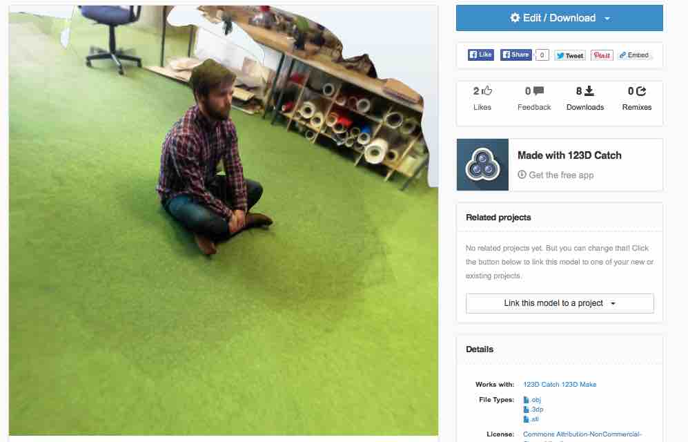
I tried a few scans of a small lego object, this proved difficult to get a good result as the details were smudged in the end design. My top tip for using this app is to use reference points around the object which help the camera to know where is it when being oirientated, this helps to remove background later on. I then opted to try and scan something larger so I asked my colleague Kasper to model for me whilst sitting. This gave a good result that I can take into the 3D printer software and 3D print.
My verdict on 123D Catch is good as I can easily take photos of the object and then send them to the cloud for processing. It does take quite a while for it to do its magic but it can give some great results.
Agisoft Software
I was going to use this software but my colleague Kasper had real difficulty working with the GUI, therefore I will put it aside for now. I am getting great results with 123D Catch and Skanect at the moment anyway.
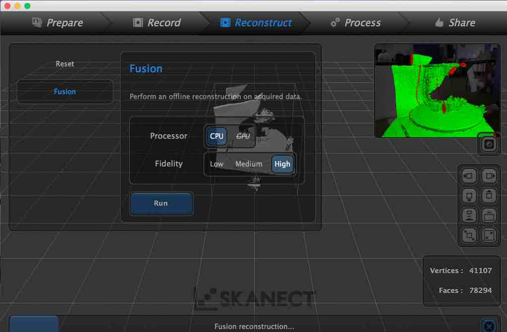
Skanect
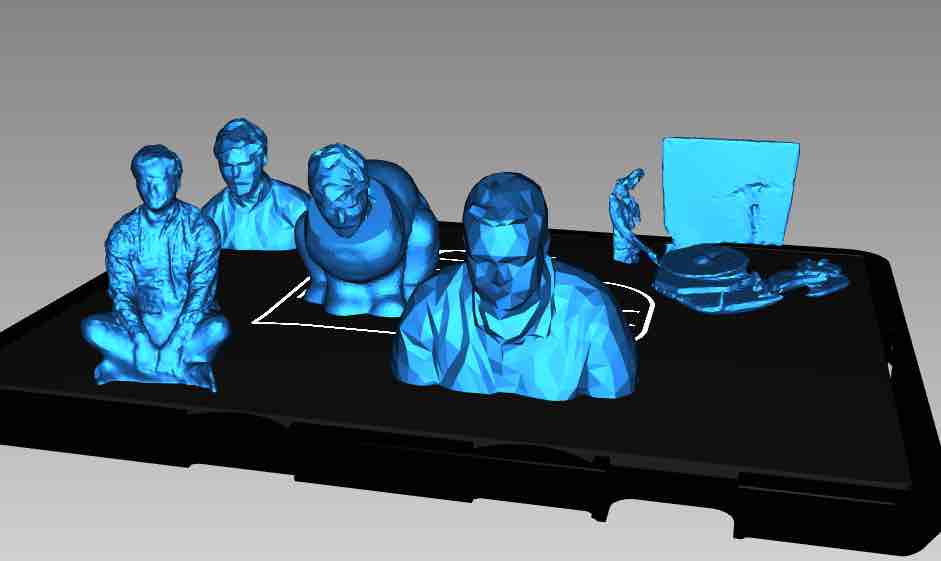
My first chance to play with Skanect was not very good... I tried to 3D scan a small lego car I brought into FabLab, there was a distance issue which meant I could not get the scanner upclose to get good detail, everytime I turned the lazy susan platform, it warned me that the speed was too fast for it to keep up. I decided to scan something bigger, my colleague Kasper and I took turns in scanning each other, to see how it works. I was very impressed with the process but the software is very slow to run and crashes whenever there is a breeze.
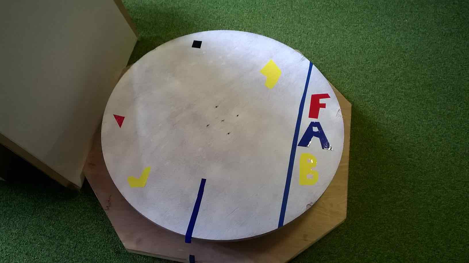
My colleague Kasper and I spray painted our lazy susan stand, and added stickers to it. This was to try and help with making sure the camera knew the location of the object in relation to other objects. We also have plans to create a photo-booth style unit that the user can put their model inside, and it would automatically rotate the model whilst scanning it. Watch this space.
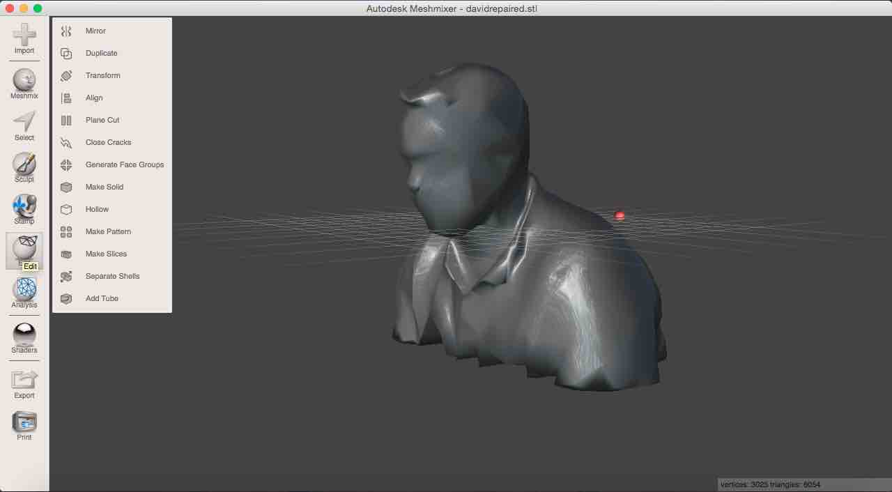
Netfabb and Meshmixer
I was quite daunted by both these software as I have never used them before. After playing with them for a few hours, I have come to notice how useful both these software's are for working with 3D scanning objects. It is no surpise that I have not done any 3D scanning before so I have not come into contact with these software (though I should start using Netfabb for the repair of my .stl files from now on. I could use Netfabb to do general repairs and cropping of my original scan, and then I could use Meshmixer to do some 'artistic license' with my models such as putting my colleague Kasper's head on a rabbit. This involved manipulating the stl on all the planes and then importing another .stl before doing a boolean union. I still have much to learn with both these software packages, but I plan playing with them more.
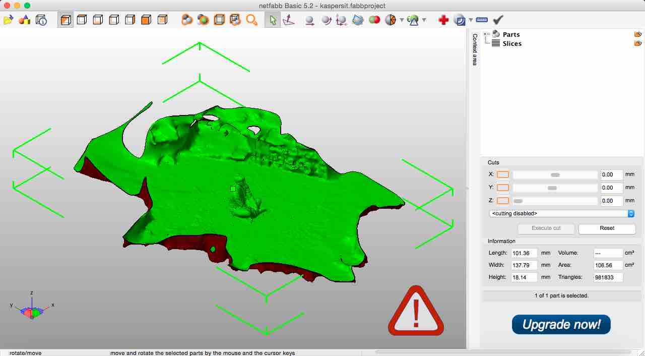
Object is brought into netfabb with errors being displayed
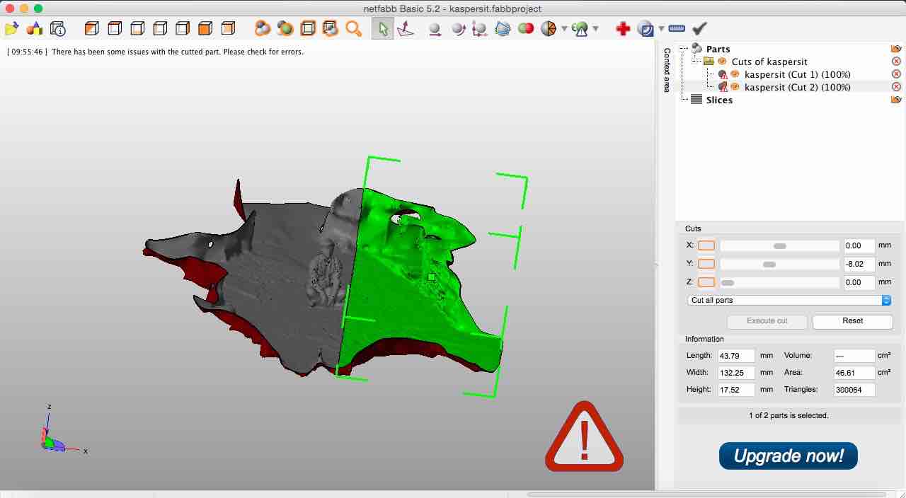
First step is to clean the background up by using the X,Y and Z planes to cut in convenient places. This simplifies the repair process for later. If the repair was done before this, it would damage the model in the middle.
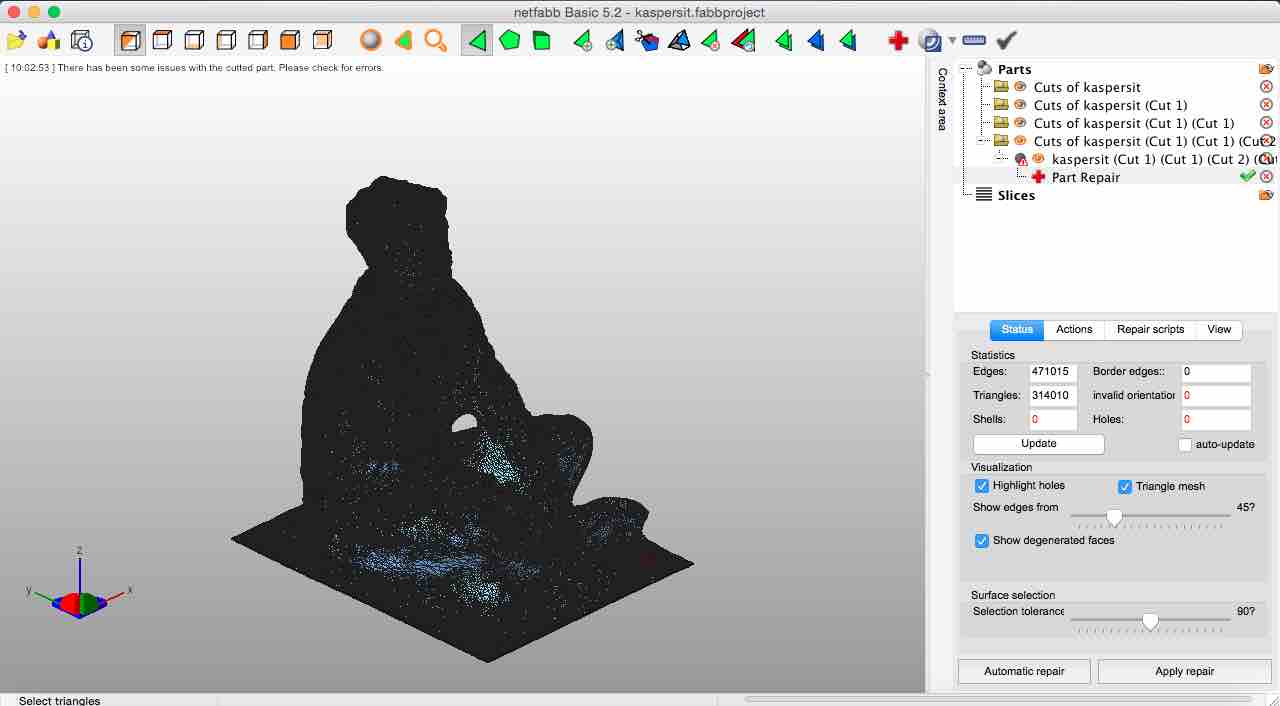
The .stl is repaired for holes, traingular placement etc
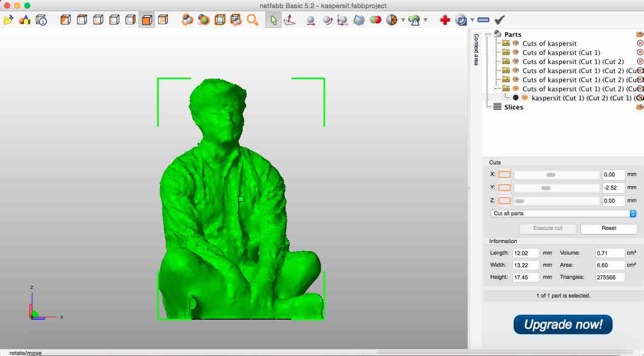
The finished model ready for printing
Meshmixer then allows me to sculp the image such as smoothing surfaces and adding other .stl files to create a new object. A very powerful piece of software, lots to learn with this!
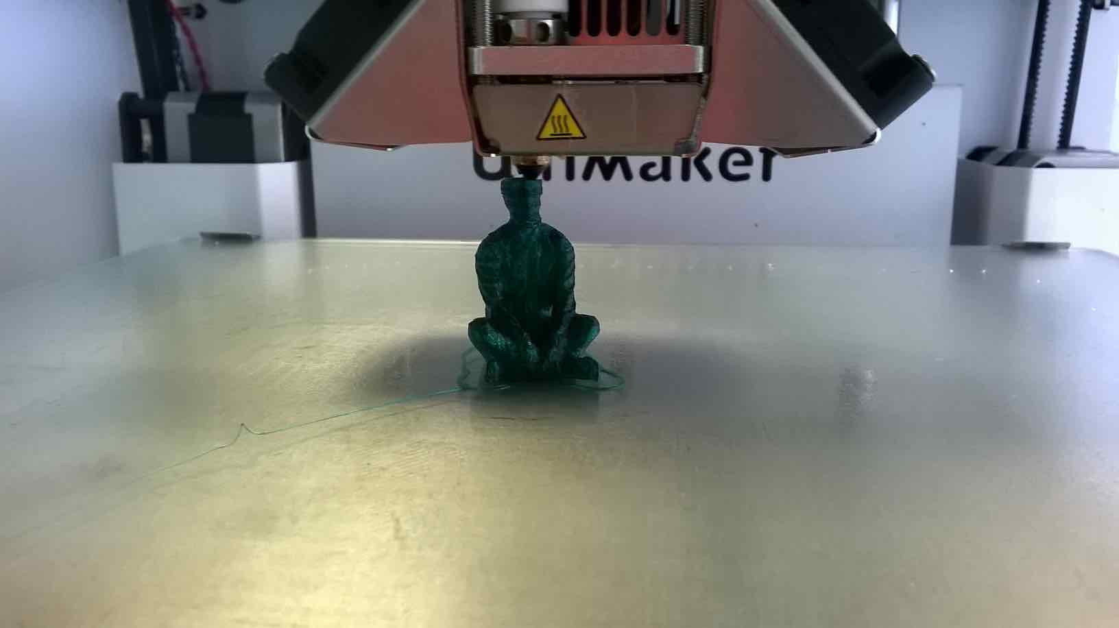
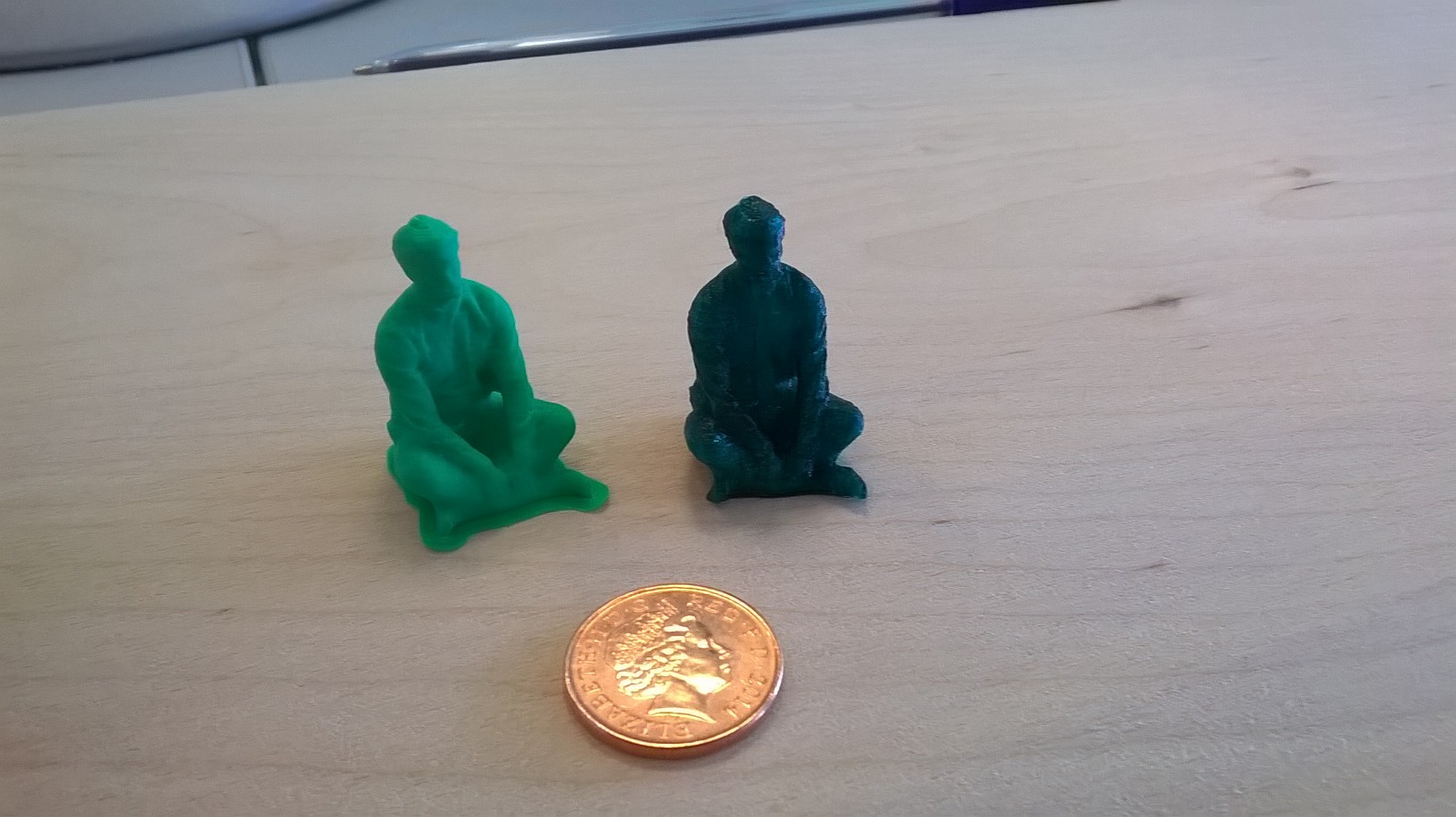
A brief comparison between Robox and Ultimaker 2
Here are two Kasper prints. The one on the left is the Robox and the one on the right is the Ultimaker. It's not a fair test because they didn't have the same material, and we could improve the clarity slightly on the Ultimaker.