After Neil's lecture, I was keen on creating a Design that would challenge me and produce a good looking result. I had several ideas for the final end product including:
A toy box with 3d textured internal walls that show 3d houses, mountains and lakes. The issue with this design is the way the box closes as we can't use fastenings such as hinges
A pizza making table that allows you to put the pizza peel on the table and slide the pizza on. I found this one slightly too simple so I brushed it off
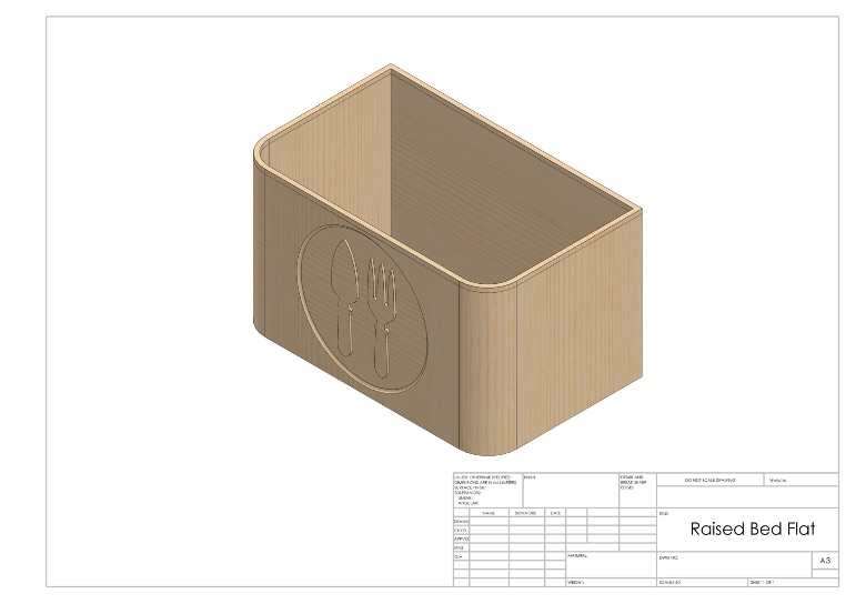
A raised bed that uses a living hinge flexure to create the corners
Living Hinge Raised Bed - Trials and more trials
As soon as I had decided to make a living hinge raised bed, I set out to create some test samples of living hinge in my 18mm chosen wood. Using inspiration from my tutor Michael's previous attempts of living hinge but I also wanted to create a sample with one side not cut through. I created a basic design in Solidworks that had 6mm living slots, not a clever design but more on this later
As soon as I had a basic design and a sample piece, I set up the shopbot. This is the process I went through to get the end result, including all initial mistakes.
From my Solidworks top view drawing, I imported it as a .PDF into the Vetric software we use in Manchester. This was my first mistake as the drawing has brought in all the extra options such as table name and outside line. This made the CNC software think that the work was bigger than it was. Next time I will try and get rid of all the extra bits and just have a drawing of my product.
Once I had got rid of the extra design elements, I told the software the dimensions of my sample piece (which I measured to be 18.1mm).
I then created a simple toolpath (a lot more on this technique later because I have not fully grasped this yet!) and saved my file into shopbot format of #####. I was now ready to cut my job
I placed my sample piece on the bed and screwed it down. If I was doing a bed size piece. I would get the software to drill the holes for the fastening to the bed.
I then setup the machine. The shopbot already had my desired toolbit in it so I was happy with that. I also checked to see that the guard was in tightly (though it has seen better days, it still works).
I then located a suitable X and Y position on the bed relative to my sample piece but instead of zeroing the Z axis, I took notice of Neil's advice on doing your first job in the air. This was very useful to see and it minimises the risk of messing up first time. It looked like my tool path was following my desired route.
I then zeroed the Z axis by using the zeroing tool. This is a simple device that creates a circuit between a piece of metal layed on the bed and the drill bit (with a clamp attached). When you select 'Zero Z' it asks you to put the piece of metal underneath the drill bit. The Z axis then drops until it comes into contact with the plate. Once this happens the Z axis goes down another time for minute detail of the correct position. This then saves the Z axis along with the offset for the metal strip.
Final checks before proceeding:
All axis are zeroed in the correct position.
The drillbit is in tight and is running at the desired RPM.
The guard is tight
The filter system is on and running efficiently
All PPE is worn for protection including safety glasses and hearing protection. Not much dust from this so no need for breathing guard.
All safety buttons are located
Once all this is ready, hit START
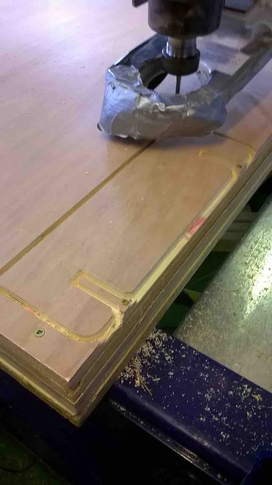
Well this is where my first mistake was obvious. I notcied the toolpath following a strange route as it was joining all the holes and creating a mess. After this I stopped the machine and got assistance from James Fletcher. He noticed that my design had open vectors (something that occurs reguarly apparently) so I needed to go back to my software and close all vectors within 5mm of each other. This worked a treat and I was able to resave my toolpaths, but this time the software did not like to have a 6mm hole and a 6mm drill bit. I then had to go into the tool options and make it think the tool was 5mm to resolve this. Next time I may just create a line and ask the software to drill on the centre of this line
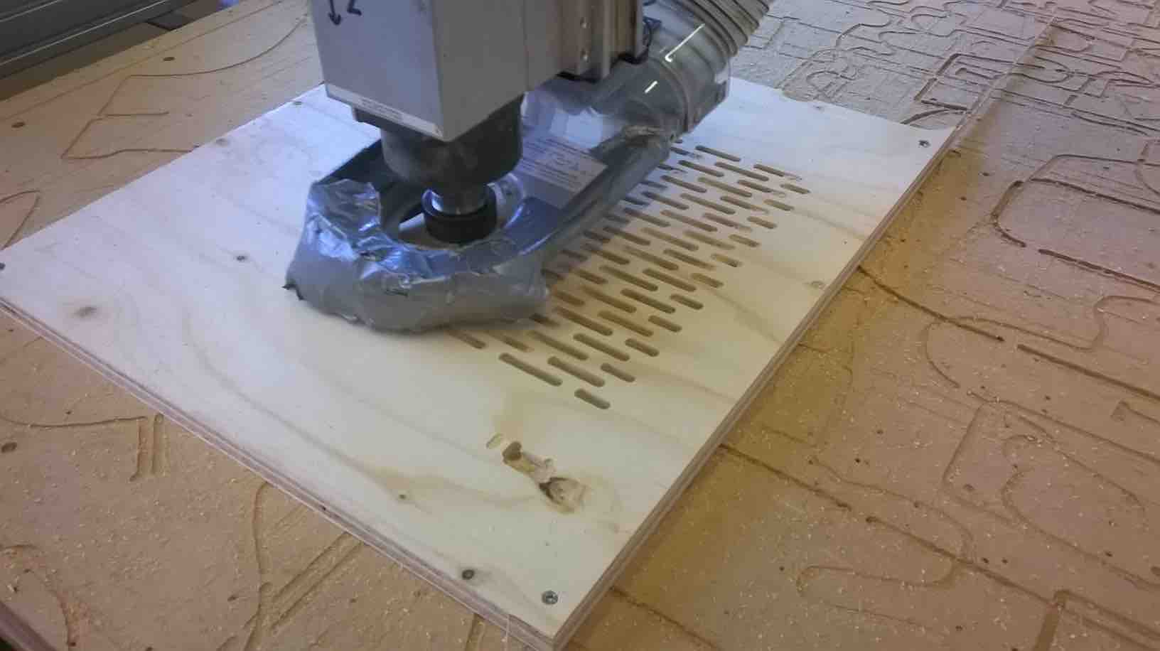
Machine setup again but with the vectors closed and the option of ramping the drill but (gradual incline into the material). I started the machine but noticed a new problem half way through. The ramping was starting higher and higher up (or so I thought) and was not going through the material all the way. Another bit of assistance from James, showed that the drill bit was tight but not tight enough as it was going up the drill shaft. So another tightening and restarting from the zero positions, I started again. Success this time
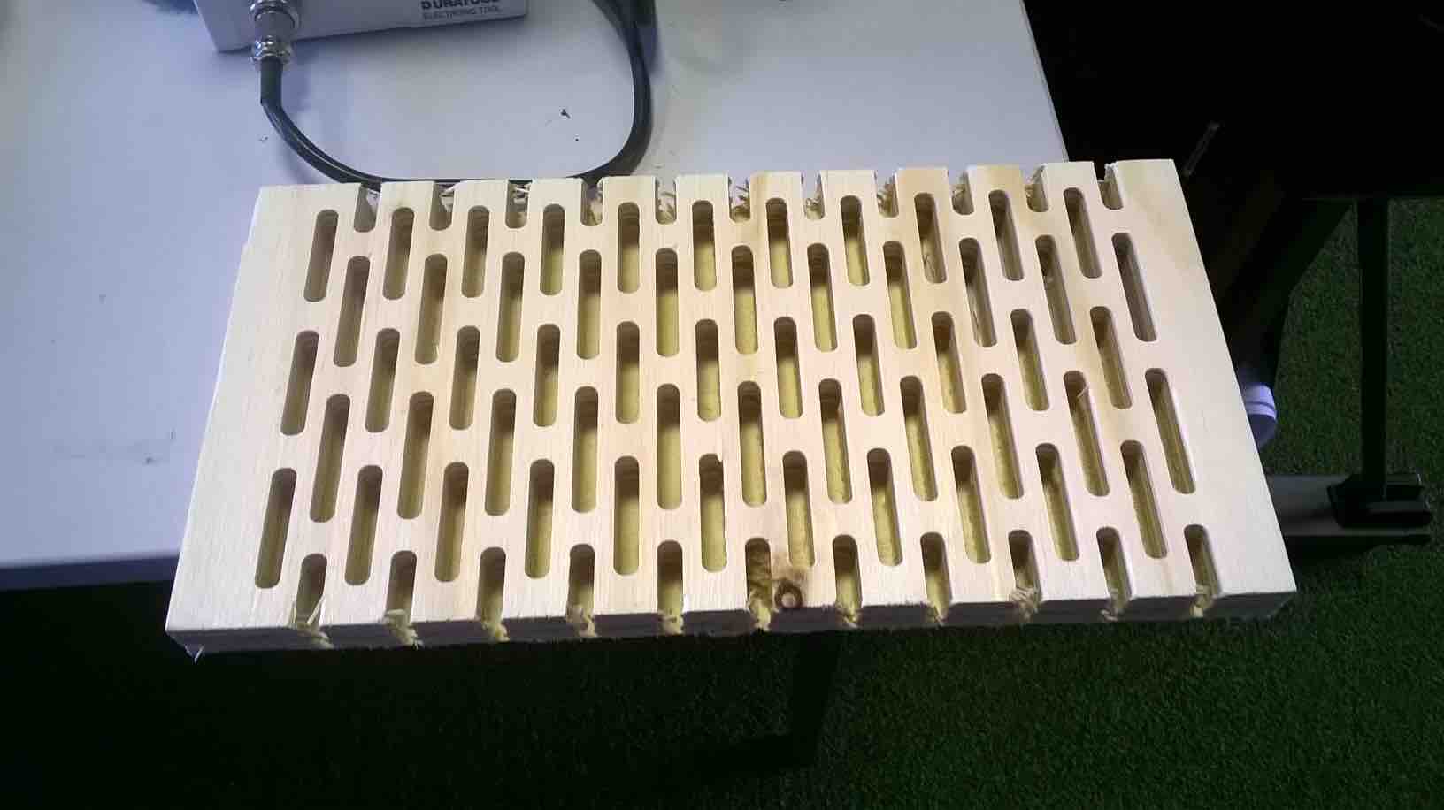
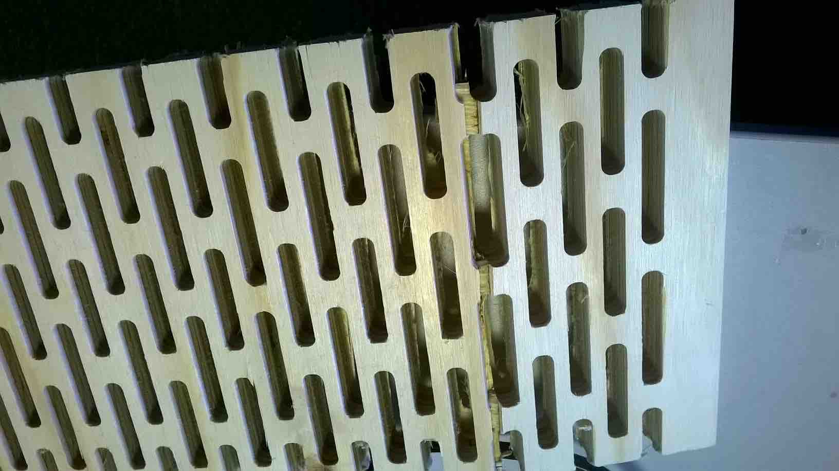
Well the milling finished but the living hinge did not work as I hoped it would. I put this down to a few issues which I can iron out hopefully. First the orientation of the grain was not correct as the it opposed the bend. Secondly my Solidworks design didn't have a uniform cutout shape with the second internal shapes being slightly different size. Finally the hole size may have been too small for the living hinge on 18mm wood.
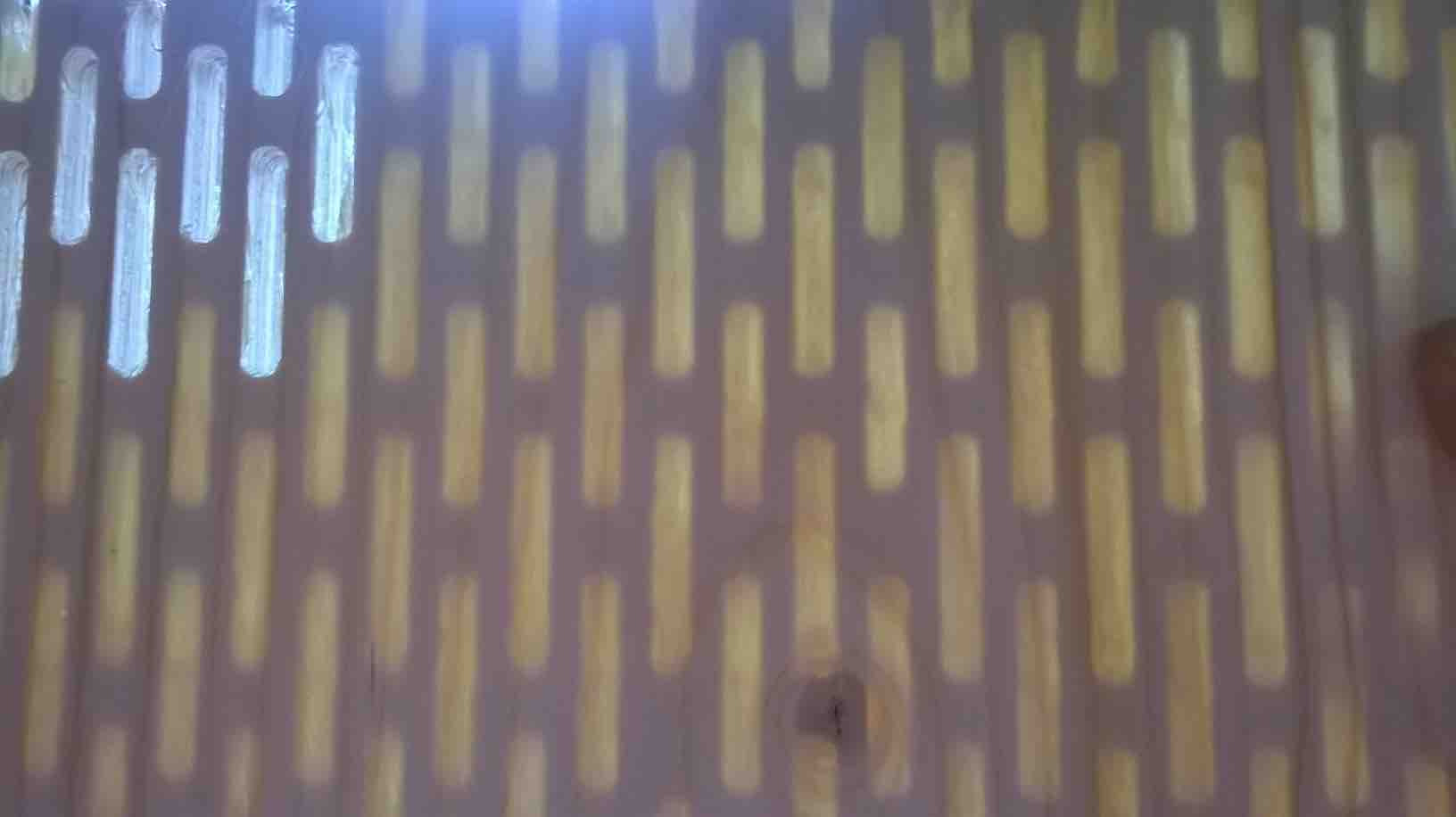
One shining light from this design was the end with the solidwood layer (1mm thick) created a cool effect for light passing through it. This will be useful for future projects such a LED Clocks with wood front.
Guide on creating Living Hinge shape in Solidworks
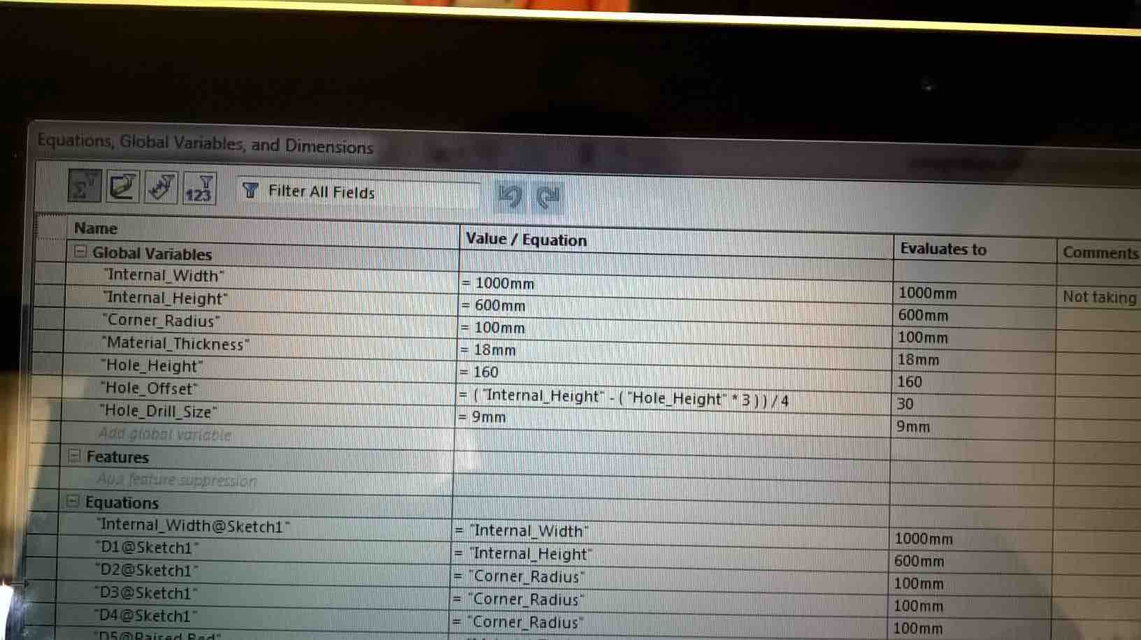
After not getting the best results with my living hinge, I wanted to create a 'programme' in Solidworks that would automatically adjust the slots in the living hinge without the user having to set the measurements. I achieved this by using the Solidworks global dimensions, which sets global parameters over the design. The holes in my design were set to 30% each per height of wood. The remainder (that being the gaps) are set to the final 10% which is divided by 4. Here is a picture of the global variables, the design file is in the download section below.
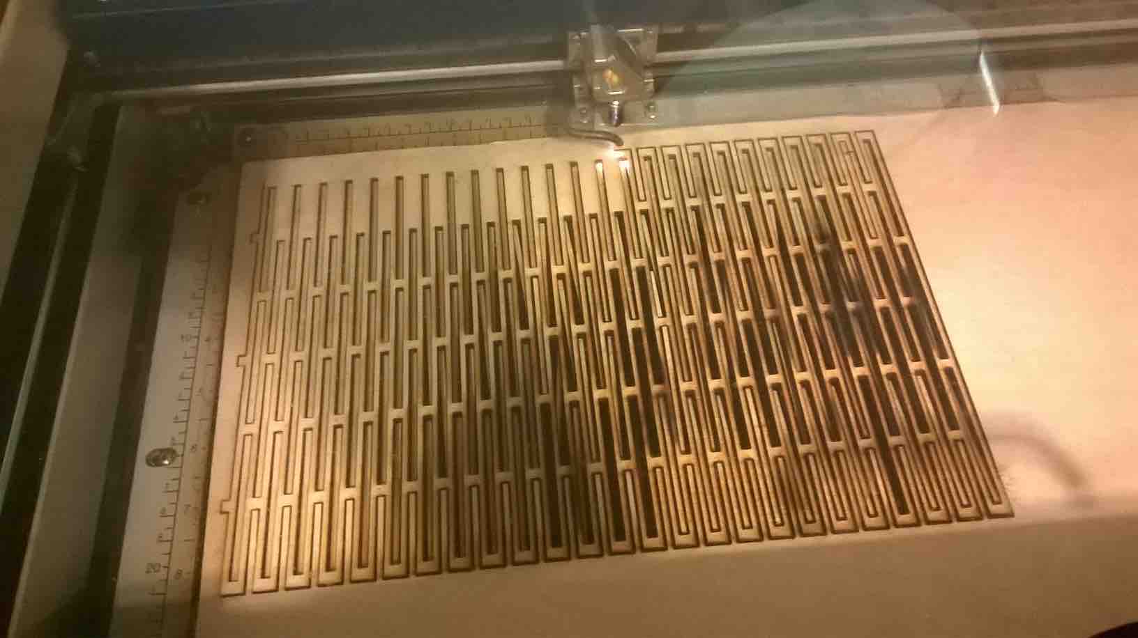
I tried my design on the lasercutter, as my programme doesn't require you to set the depth of the material. This worked really well with the living hinge but it took ages to cut so I don't recommend doing large pieces!
Designing a living hinge raised bed
Well this was a few days of nightmare designing! I knew what I wanted to design, and I knew I wanted to incorporate a living hinge corner design. After playing with living hinge designs in 12mm ply, I knew that there will be significant pressure on the corners due to the hinge being under constant stress.
I worked for days on coming up with a design that would a) hold the living hinge tensions/soil and b) to create a design that doesn't require fastenings. I tried using the sheet metal tool to create the shape of the box, this worked well because I could create the shape and then lay it as a flat shape. The problem was that when I extrude cut the living hinge edges, it would extrude cut everything except the living hinge holes! I was also struggling to work out the shape that would occur when the box is made. I also needed more time to work out how the base would slot in. After much 'soul searching' and countless hours of working on it, I decided to put it aside for the time being and work on something simpler that gradually inclines me into CNC milling. I will definately come back to this project and the toy box when I have time!
Pizza Table
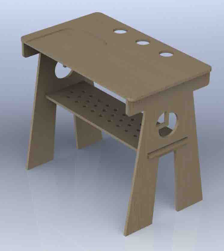
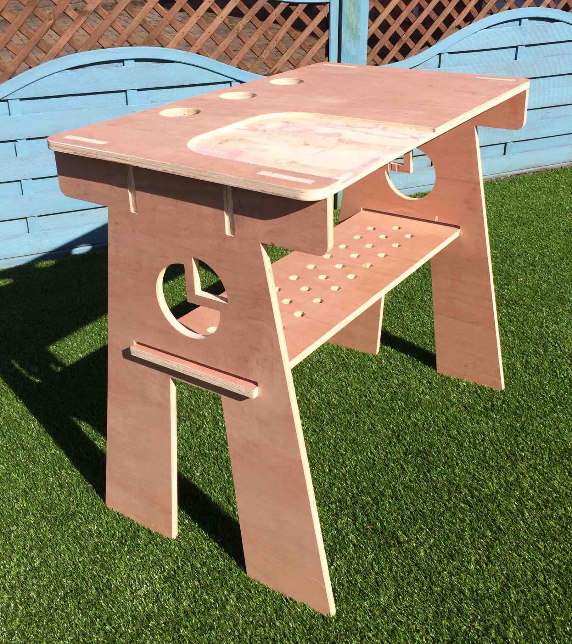
This was a project that I wanted to do at the start of the week, but I did not think it was worthy of a good looking project. The idea for this Pizza work bench is in Naples, when working on the pizzas they use a small lip on the table surface to allow the pizzas to be slid across onto the peel and into the oven. This is usually a two man job (though can be one if the pizza place has a hook to put the pizza peel on) so I thought about creating one where you can slide the pizza on and then put it in the oven. I got inspiration from an open desk design called Olivia (see top left) which was a basic design for a table. I then took this inspiration into my design but embelished it.
There were some difficulties with this design as the legs were hard to estiamate how they would sit when finished, and also how much the table would rock when finshed (it is quite high for a table). After I had created a model in Solidworks, I then took it into FabLab on Monday morning almost ready to cut. Michael, my tutor suggested adding a bar on the legs to give it more stability. I found this to be a good suggestion but I also wanted to make use of the space so I created a shelf to store things on. The final issue I had was with the thickness of the wood not being 18mm so I had to go in and manually change the sizes. I had done some global parameters but not across all of them. Next time I will create a global text file and make all the parts share that file. I need more practice in setting distances in Solidworks that won't be affected by the change in size of the material.
Shopbot Final Cut - Pizza Table
Once I had the parts ready to cut, I went about getting it ready on the Shopbot. Here is a description of what happended:
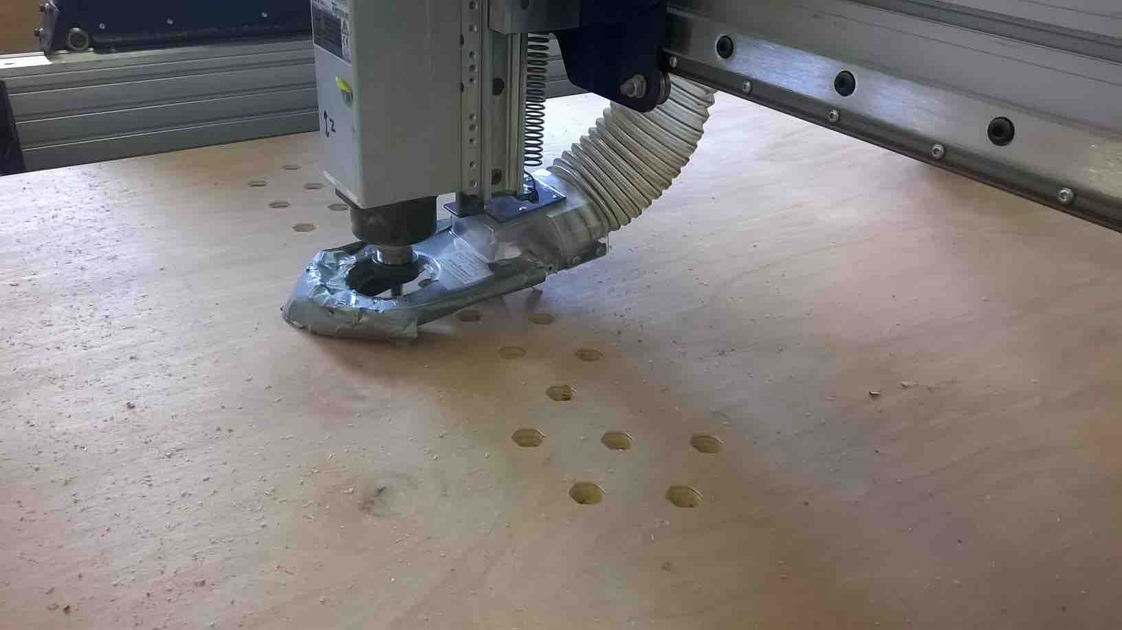
Setting up the Machine: With the help of another person, the wood is brought onto the bed and is screwed in all 4 corners (I cold have done more but the sheet was very large and not giving much so I was happy not to waste material space. To screw it down; first drill a hole the same diameter as the screw and then screw into the wood and half way through the sacrificial bed. The reason we screw a hole the same size is to prevent the wood being dragged down to much in the corners. Careful measurement should be taken where the screws are on the bed, to prevent the machine from milling over one. A new drill bit is 30 quid!
The X & Y co-ordinates were then set to the corner of the bed with the drill bit being the focus of the origin. We then asked the machine to move out into the bed so we could get a better representation of the Z axis. We then used a Z plate to measure the Z. Zero co-ordinates set.
The drill bit was changed to a 12mm down cutter. This was important because some of my jobs required large areas to be cut out and the 12mm bit really shortens the length of the cut. To change the bit, use the wrenches to remove the previous bit. Remove the collet and replace with the appropriate size. Place the drill bit in until the flutes are all showing and tighten very hard. Place dust cover back on tight.
There are quite a few options for when bringing the design into the CNC software:
First of all the material size is selected and the thickness of the material
All the parts are then imported into the design and located in convenient places. The nest feature didn't work in this instance, perhaps because all the parts had to be grouped
All objects had the vectors closed to allow the software to see where it should follow (had that issue before) and some had to have extra lines added to ensure it could complete the job if two different routes went on that line. We made a mistake here and forgot about one the pocket designs but thankfully it is not a vital part (just make it look prettier on the outside).
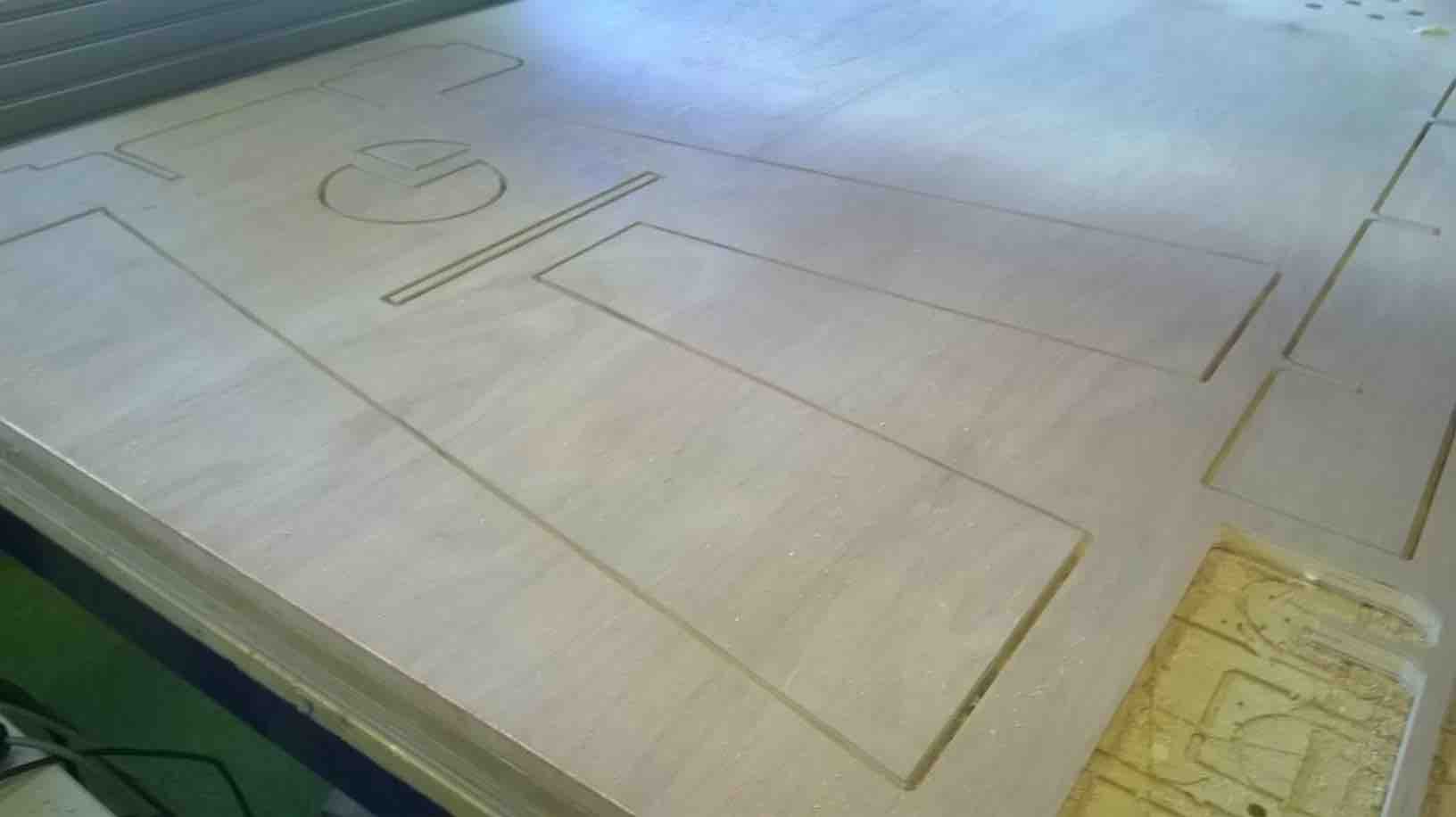
Once all objects are cleaned up, we then went and created a few different tool paths. We started with the larger drill diameter jobs such as the pizza peel top and the shelf/top holes. These were done using the pocket tool to remove all the material. This made it easier to get a faster end product because there wouldn't be any tabs to mill off (though it does take longer).
All 6mm drill bit jobs were saved as routes including the final cut out of all the pieces. We selected several options in the software such as tabs on all parts, ramping the part (this brings the drill bit in gradually to the material) and also selecting the speed. The speed of the bit is an important factor. With an increased drill bit diameter, it is possible to increase the speed to remove the material faster. Michael used imperial measurments to show how this worked and showed how the speed in inches is in directy relation to the size of the drill bit.
All toolpaths were saved. We saved the toolpaths for the 12mm and 6mm into their own groups so it would do all the 12mm jobs at once and all the 6mm jobs at once.
Send the job to the CNC machine and watch it do its thing
Distaster! When bringing the machine back to its origin between the 6mm and 12mm bits, I pressed the X position on the keypad and it skipped a few turns on the motor. I knew instantly this was a big problem, because it no longer knew where the origin was. Luckily Michael heard the noise and had a plan. He drew a circle on the diagram relative to one of the parts and the size of the drill bit. He then located the co-ordinates for the centre of that circle and wrote them down. Turning the machine off at the well, he dragged the drill to that point on the bed (corner of a rectangle) and dropped the Z until it was just in the corner but not touching the sides too much. Michael then turned the machine back on and asked it to go back minus the co-ordinates from the circle. This brought it back to the corner again, a very good save that I would not have known how to do!
Here are some photos of the milling stage and a short video
Feed and Speed Settings for 12mm Down Cut 2 Flute
Feed Rate: 6 Inches per second
Pass Depth: 6mm
Ramp Setting: 10mm (I tend not to make this too large in case of mistakes in the code)
Stepover: 50%
Plunge Rate: 0.8 Inches per second
Tabs: 4mm (depth) x 4mm (length)
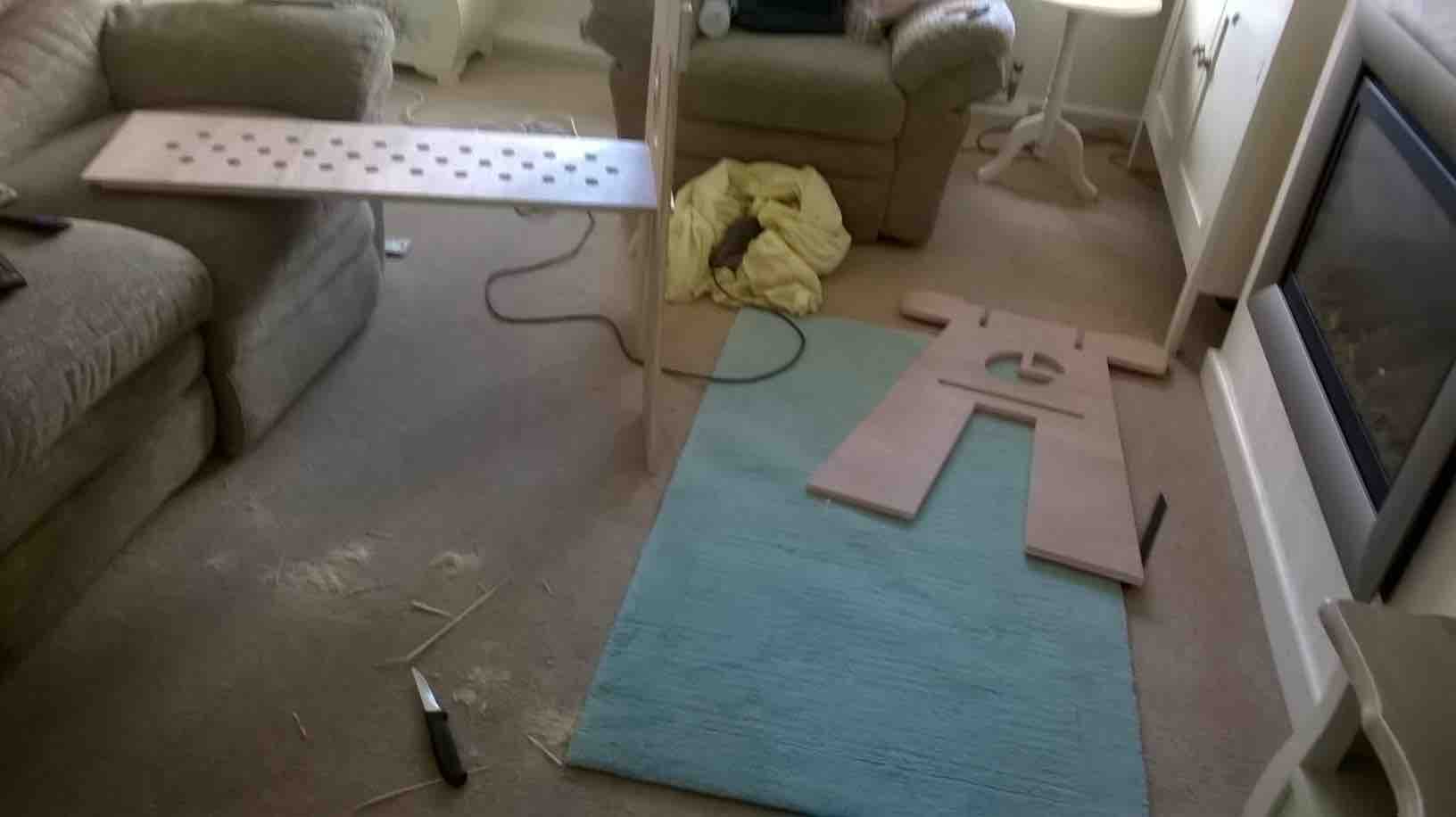
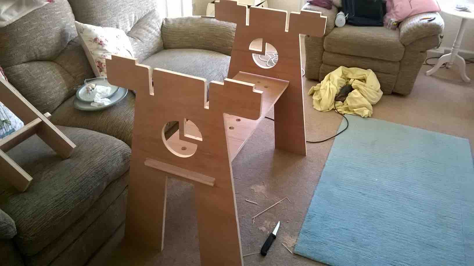
Putting it all together
I have to say, I didn't think the assembly would be such a difficult part of the task. My sheet of timber had slight variences in the thickness all the way across. Which when putting the parts together made it really difficult to slot together. I had to go and buy a metal file to actually smooth down the edges. I didn't think this would be a problem because we did a sample slot design in the wood which went together really well, but this was in the same location.
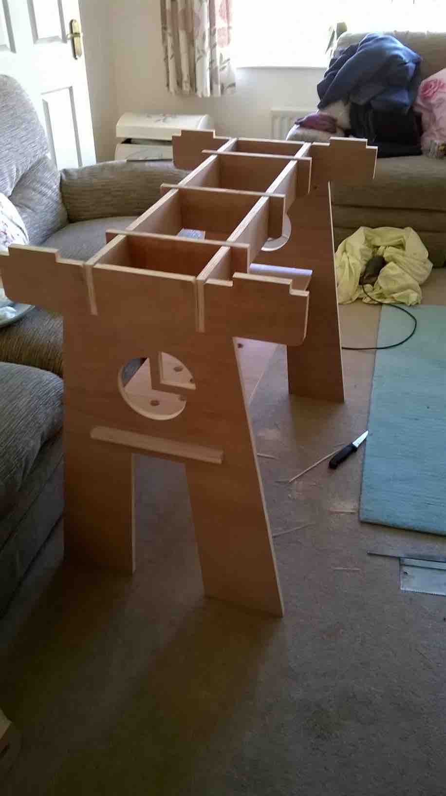
As soon as it was all sanded down, I was able to slot everything together (with the assistance of a rubber mallet). It took a while to get the locations just right but it eventually all fitted together and is now ready to be varnished for a more natural look and for food use. Here are images of the final assembly.
My Downloadable Files
Solidworks Files - Living Hinge and Raised Bed (DropBox)