Designing and Making One’s Own Fabduino, and Resisting the Urge of Calling it the “Fuck-it-duino”
This week’s assignment has been, for me, the most time-consuming, effort-intensive and overall… anticlimactic one of them all. As my mind is, like I first mentioned last week, slowly settling on building a rotational casting machine for my final project, I dedicated the input and output device weeks to making bits and parts of it. In that sense, I decided to make a system able to translate inputs from a potentiometer into motor velocities and, to make everything easier (well, that was the initial intention), started working on my own version of the Fabduino as a way to bring together these inputs/outputs.
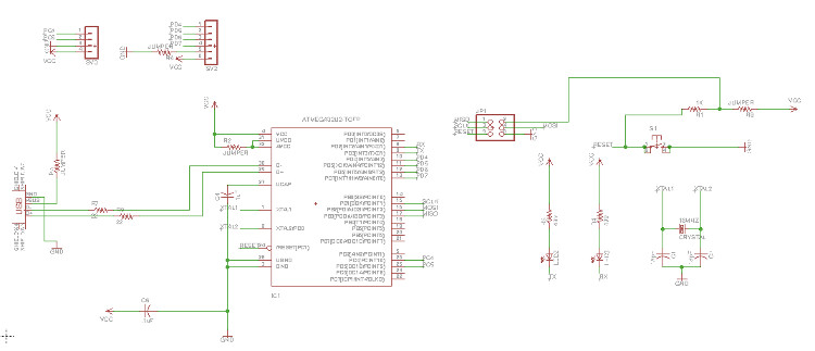
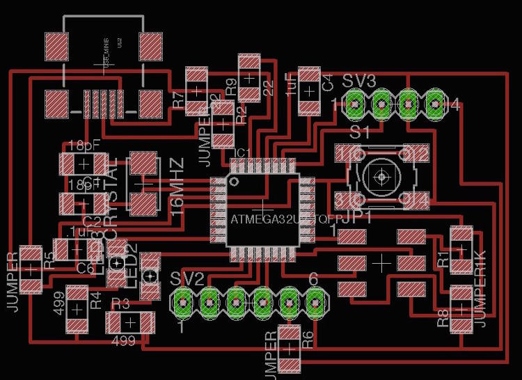
I therefore spend most of the week designing the said board. Ferdi recommended me to work with the USB-enabled ATmega16u2 chip, which I welcomed as an interesting challenge for I couldn’t find any similar fab-board using this chip. The first half of the week was pretty much a big puzzle, as I could only loosely inspire myself from Neil’s Fabduino, Fab Lab Barcelona’s very own Barduino, and the schematic of Arduino’s Leonardo board, which relies on the same chip. I therefore became quite close with the ATmega16u2’s datasheet (marvelous bed-side table reading) and tried to fit as many ports, bits and pieces as possible on the smallest surface I could make them fit. I was indeed quite happy of the resulting size which was something like 1.35 by 1.42 inches, but ran into my first major problem at this point when I realized I had been designing my board with the ATmega16u2 mini schematic, and not the bigger one that we keep in the inventory.
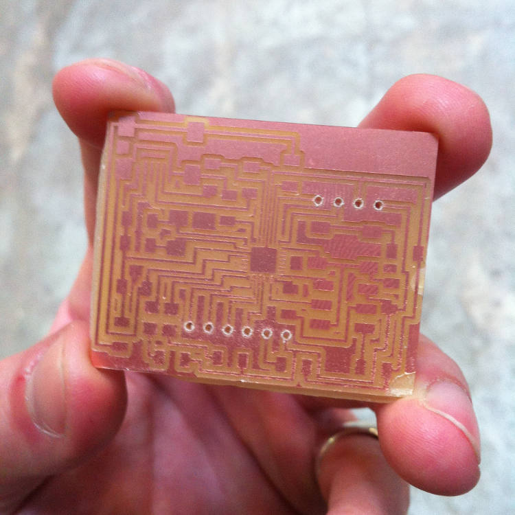
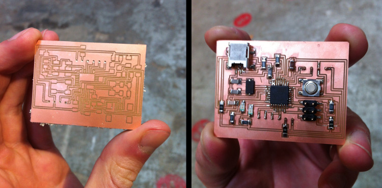
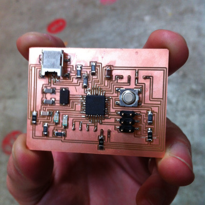
This first hair-raising pickle put behind me, I quickly redrew the whole thing with the bigger chip and milled it using the 0.010 mill – the smallest one that we have in the inventory. I indeed had to reduce the size of some bits of the sketch directly on GIMP so it could be cut in the Modela, but the milling went quite well otherwise – using the 0.010 for the traces, the 1/64 for the holes, and the 1/32 for the outline. I then could solder every piece on the board, which went surprisingly well despite its small size – I really feel like I am getting my head around soldering.
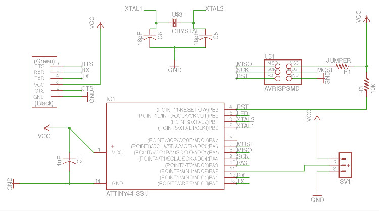
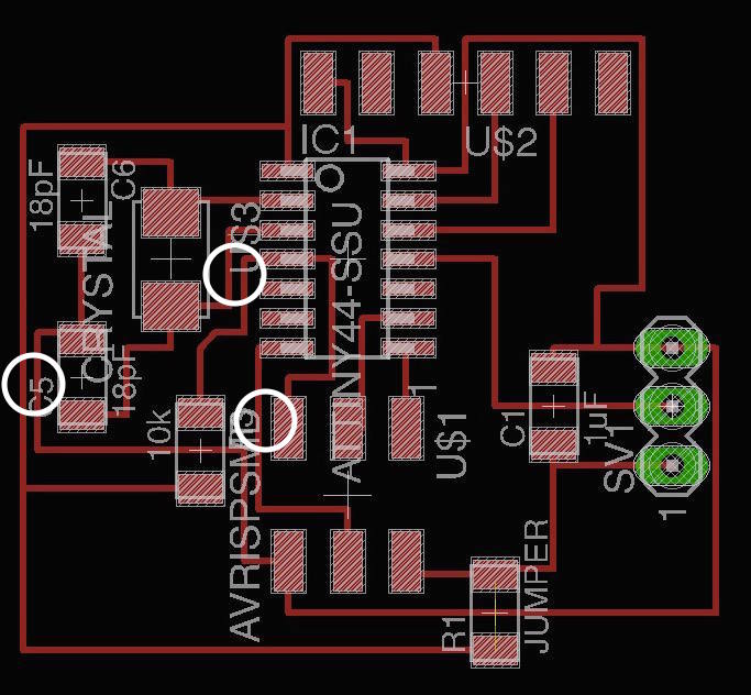
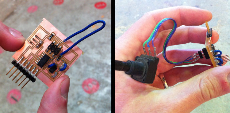
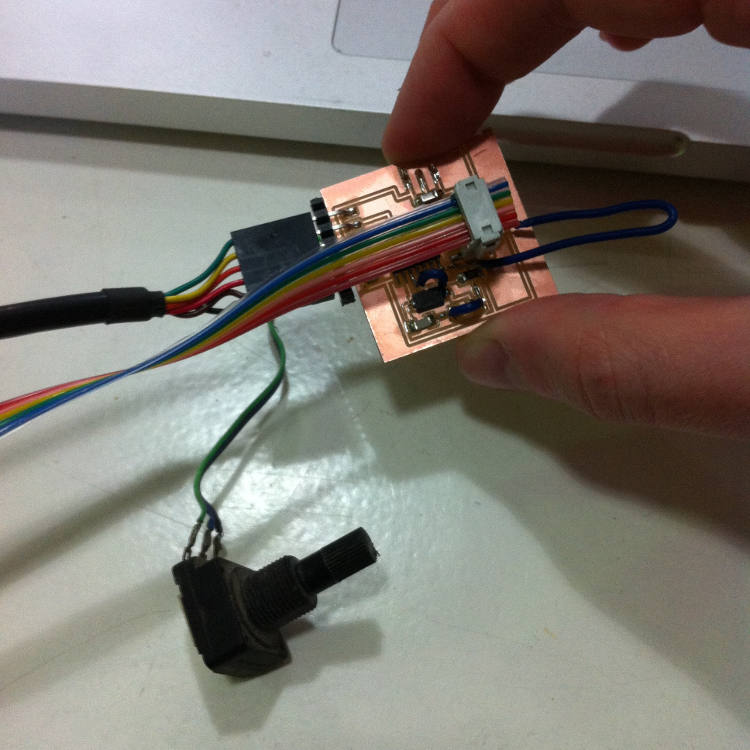
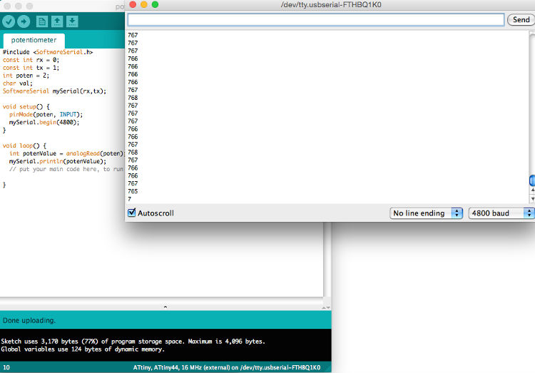
Unfortunately, as I was running short on time, I couldn’t really test my board – it was already Tuesday at this point, and had to think of a plan B in the very likely possible of the board not being usable in the short run. You can download the schematics and the board files here, but I will probably have to update them next week, as I will (quite certainly) find mistakes in them. In the meantime, I quickly designed a second, smaller board with the ATtiny44, a 16MHz clock and some inputs to connect a potentiometer (click here for the files). At this point, I was getting quite anxious of milling, soldering and making the whole thing, and, unsurprisingly, made few design mistakes (I had some lines connected where they shouldn’t have been – always do your design rule check, kids) that I could luckily get across with some jumpers. The resulting piece is quite ugly, but it’s working – I had spent so much time on my own Fabduino (still need to get a name for it, if it works at some point) that I couldn’t really spend much time on C, C++ and Python, so I simply wrote a simple Arduino script measuring and writing using serial communication the "twist level" of a potentiometer (available here), which worked smoothly.
Let there be Input from Theo L. Richer on Vimeo.
Next week, I will finally try to program my Fabduino (so far, my computer recognized it as a USB device, which is already a big victory) and come back with more news about it. Hopefully, I should be able to use it to bring my input and output devices project onto a single board!
See below for all the details/for each step.
- Week: 10
- Subject: Input Devices
- Tools: Eagle, GIMP, Modela, Arduino
- Objective: Measure something: add a sensor to a microcontroller board that you've designed and read it
- Files: Click here
