what is needed?
software: rhino, vcarve
tools: shopbot with a 6mm upcut bit, sandpaper, hammer, file
materials: 20mm plywood
location: Green FabLab Valldaura (BCN)
how to:
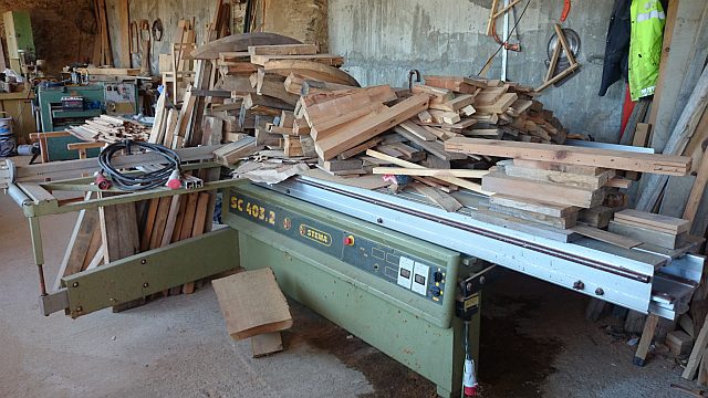
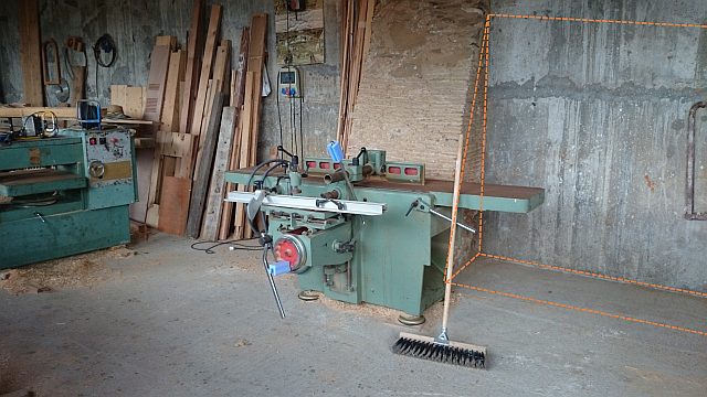
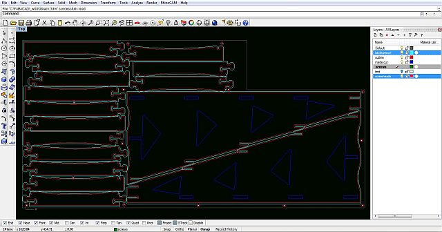
in the process of cleaning the carpentry i came across a lot of nice pieces of wood, the type you always need in a carpentry. since they were stored in an unfortunate place i wanted to make a shelf which is also self-organising. adapting the shape of the shelf to the shape of an existing retaining wall left me with a triangular design, the bottom giving space for the longer pieces and the further up the smaller the pieces have to be.
the shelf should allow a maximum flow of air to keep the wood dry and prevent mould or a nice environment for wood-munching bugs. the idea is also to have a pressfit construction, no screws no glues. therefor i don't have any tolerance in the joints (and use a hammer to connect everything)!
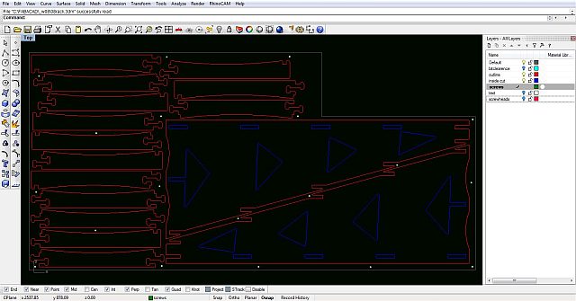
the first thing to draw is the outline of the available material (the grey line). therefor measuring the actual material is vital, i meassured a different board assuming it is the same size. consequently i had to redo the nesting because the board i used was smaller than the design...
at first i wanted to make only whole pieces but it would have been material intensive. following an advice i chopped the horizontal parts into four pieces.
to make the production easier, everything should, according to the cutting-strategy, be on seperate layers. in this case:
- red: outside cuts; the milling bit follows the line, only tangentially "touching" it on the outside
- blue: inside cuts; the milling bit follows the line within the geometry
- green (white dots in the picture): screws; the milling bit will only mark the position of the screws which will attach the board to the machine
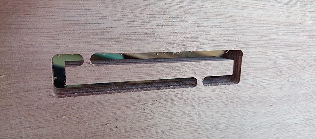
every radius should be at least the same as the milling bit that will be used, for the dogbones i used a 3mm radius, which didn't come out as good as expected.
nesting
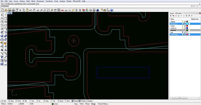
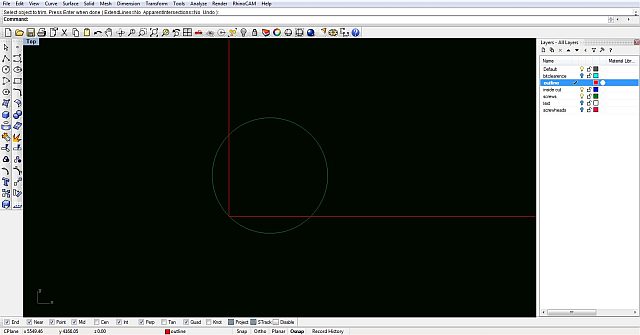
nesting is the process of arranging the pieces on the board after finishing the drawing and before milling. a nice way is to make an offset line (cyan) around the objects (red) with the distance being the diameter of the milling bit. if the cyan line crooses a red line it means the bit will cut into the object. i found this being a very handy strategy of being accurate in the nesting and it actually made another piece fit on the board.
also the diameter of the screwhead should be drawn around the points representing the srews. additionally i made another offset around that to have a visual control of the nesting.
cutting strategy
- load the .dxf file in vcarve
- choose the tool in the tools-library
- define the stock, thickness and size
- first set up the srategy for marking the screw positions, therefor select the objects on the "screws" layer and apply a drilling strategy with a depth of only 3mm
- execute it, screw the board to the shopbot
- now set the rest of the strategies, first the inside cut and then the outside cut.
- using 20mm plywood i defined 5 passes to get a nice quality of the cut and make sure the milling bit doesn't suffer too much
- to make sure the pieces stay in place after being cut out make tabs, if not things might fly and hurt!!! little pieces like this might get caught by the milling bit and take off or break the bit.
generate the gcode and safe it.
milling

- on the side of the machine swith the power to "on"
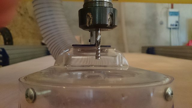
- open the collet and put in the milling bit you intend to use
- make sure it is the right collet for the bit!!
- don't put the milling bit into the collet too far, but also not too far out. if the bit is too short, the collet might touch the board, if it's too long it might start oszilating when it touches the material
- bring the extractor back to the right position and close the screw.
- go back to the side of the machine and switch the key to "engaged"
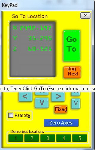
- with the keypad it's possible to control the movements of the machine in all three axis
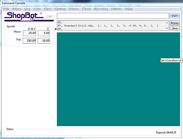
- in the command console it's possible to talk to the machine. since the shopbot in the green fablab has proximity switches, setting the x/y 0 is easy. there's a command called "set the x/y 0 with proximity switches". it's good to use the machine 0, if a job is interrupted for whatever reason it's possible to restart it without loosing the precision.
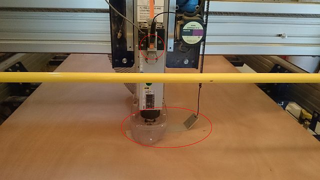
- to set the z 0, the shopbot has a plate and an alligator clamp included. place the plate under the bit and attach the clamp to a metal part on the milling head.
- the milling head will go down until it touches the plate creating a short circuit twice and therefor recognizing the z 0.
- now open the gcode file in the command console
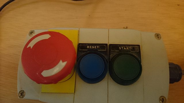
- push the start button and wait untill the the milling bit has fully accelerated
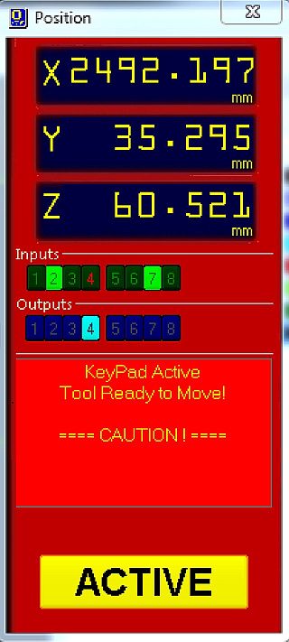
- click on start (now "active") and let the games begin.
troubles
- for some reason, probably the warping of the board or not enough screws, the material hasn't been cut all the way through. therefor i had to make a new cutting strategy, "jumping" over the tabs.
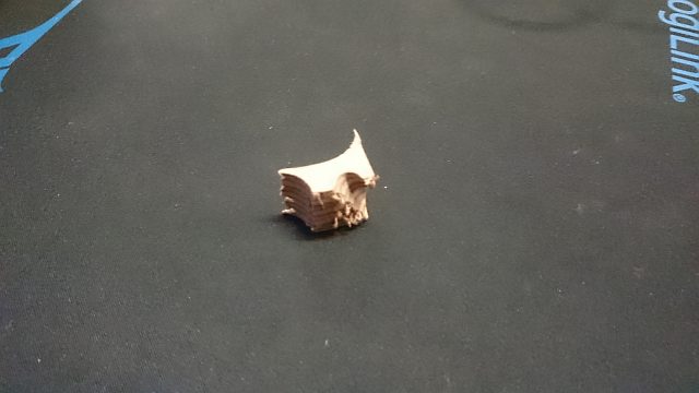
- because of the tght nesting and not enough screws and tabs some pieces got loose during the cut. since the milling paths overlapped, loose pieces got cought and provoked relatively dangerous situations. things started flying!!! in the best case it's a tiny bit of wood, in the worst it's a broken milling bit...
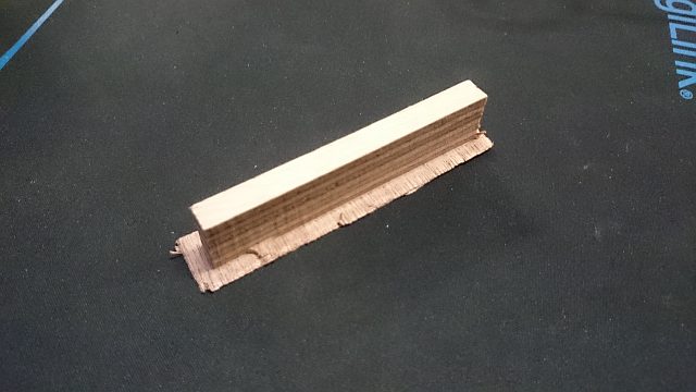
result
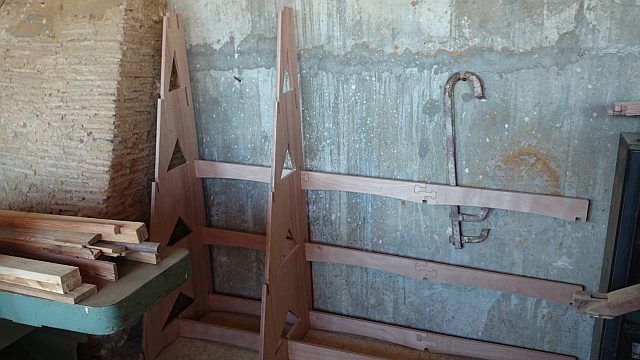
- since it's a device for the carpentry and it needs to hold quite a lot of load, i used 20mm plywood which was not in the inventory and too expensive to buy. also it is interesting to make the most of the available materials! therefor i rely on leftovers from other projects and use boards when they are available. two triangles and eleven horizontal pieces are missing but i'll cut them on the way through the rest of the academy.