6week//
This week I was working on redraw the Hello-world board adding a button and A LED (with current-limiting resistor).

This week I was working on redraw the Hello-world board adding a button and A LED (with current-limiting resistor).

• I have worked on Eagle.
• Before of all I’ve downloaded and install the new version of EAGLE for Mac.
Then I’ve installed the fab-library for Eagle
• I've wached some tutorials to understand how to start to Design the Schematic with Eagle and after that how to Printed Circuit Board Layout.
• STEPS I've followed:
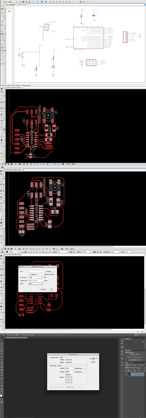
First I've put all the components on the schematics and I've connected the nets.
//COMPONENTS:
Parts Already on the Hello Echo Board:
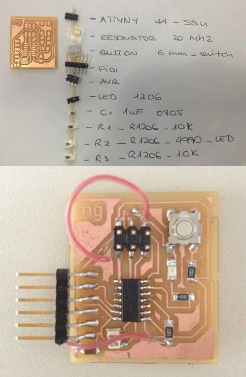
Attiny 44: microcontroller, Resonator 20 Mh2:external clock faster, FTDI header: powers and allows board to talk with the computer, 6-pin programming header.
I've add the following components to the schematic:
2 Resistors of 10K: to pull up and 1 resistor of 499: current limiting resistor to not burn the LED, Button 6mm-switch, LED 1206: have polarity, the side with the line is the cathode and connects to the Ground, 1 capacitor of 1uf.
And Ground, VCC and connect pin 10 (PA3) on the microcontroller to the button.
Then I've switched on to the board panel and I've distribute all the components on my board space.
I've check what "autorouter" conections suggest to me, but some of my components I just decide to move and connect in a easier route.
Before to export I've checked with the DRC tool the clearance is right (0,4mm) to be sure that the distance between components and traces will be milling right.
//EAGLE: schematics and board.
• I've exported my board on Eagle as image. Settings: .png, greyscale and 1000dpi.
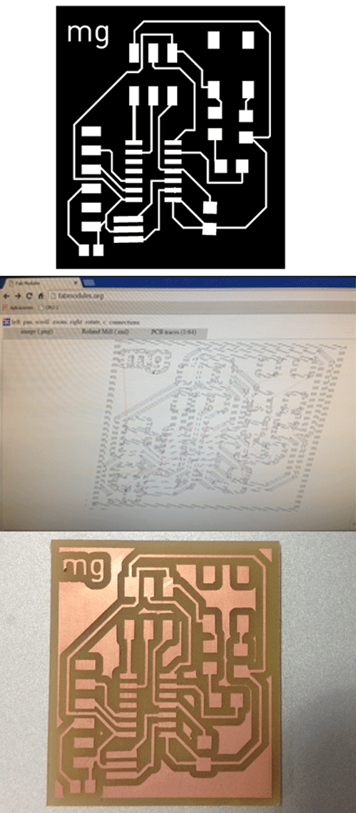
• On Photoshop I've made the interior and traces (adding 0,8mm outside to my design) to prepare the files to mill.

I've follow this steps to sent to milling on the Modela SRM-20 .
• Switch on the Modela machine
• Create the .rml files on Fab Modules
• Upload the .png file on image
• Choose the tool: 64 for traces, 32 for outside
• Choose the model of the machine: Modela SRM-20
• Set x, y and z on 0,0,0
• Setting for traces: cut depth:0,4 number of offset 1 Setting for outline: cut depth:0,5 number of offset 4
• Press CALCULATE and after that SAVE, so your .rml file is ready to send milling
• Changes the milling tool on the Modela: 32 or 64
• Open VPanel. First of all, set the 0,0 on X and Y, and then the Z going slowly till the tool touch the board. save that parameters.
• Go to CUT, delete all, add (your .rml file), press output and the Modela start to milling.
• When the traces are ready send the outline file. REMEMBER TO CHANGES THE TOOL: 32 to mill!

• When my board was milled I just soldered the components with patience. From smaller to bigger.
• I've checked on all this process on my Eagle's board the: name, place and value of the component just opening this layers, this help me to understand where to solder the component and the direction of it.
* Next week when I'll try to program my board I'll dicover some errors on my design connections and how to solve it wire. It was very usefull to undestand all process of electronic design and how it works!
• It's SOLDER!