This week's goal was milling an already designed board, weld all the components and, finally, program it using another working FAB ISP. Once I complete the assignment I will have a really cheap programmer (for just a few dollars).
FabISP
According to the "electronics production" documentation, there are several designs that can be downloaded and built.
My project is supposed to have a relatively big structure, so I decided to build the original design of the FabISP in-circuit programmer. The USB cable used to connect the computer to the device can be handy to program the board without removing the circuits from the chassis.
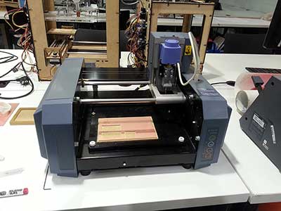
Milling the board
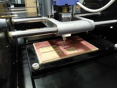
Familiarizing with the tools that are going to be used is always a must. Specially when the machine is dangerous (OK, probably you won't press the milling button while your hand is between moving parts, but just in case!). Therefore it is crucial to analyze the possibilities of the machine. From then on, we can safely operate with the MDX-20 Modela milling machine.
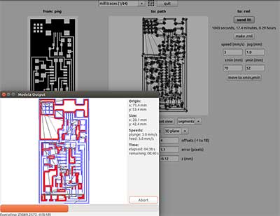
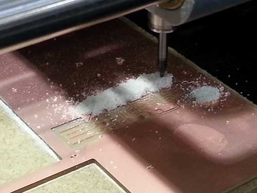
Once downloaded the images with the desired circuit schema, the milling process begins. I used fab modules and its integration with the Modela.
The process is quite simple:
- Load the *.png file.
- Select the drill (1/64 inch)
- Check that the diameter of the mill is correct (0.4 in this case)
- Set the offset and the overlap, these two parameters allow us configuring the thickness of the removed area around each path.
- The machine has to remove just the copper layer. But there is a problem, the copper board is not perfectly flat. That’s why a threshold should be added in the z-index (an extra 0,02mm) to ensure that all the paths are properly defined.
- Once all the parameters have been set, it's time to click on "make .path" and check that everything its OK in the image above.
- Set the drill in the origin. Moving the drill to the start coordinates is quite easy, I measured the distances in mm with a ruler and wrote the desired values. To set the 0 value in the Z axis, I ensured that the drill was touching the copper before starting, to do so, is advisable to push down the copper board before adjusting the mill.
- Set the speed to 4 (I chose 3, because the drill was new).
- Press on "make .rml".
- Print the circuit.
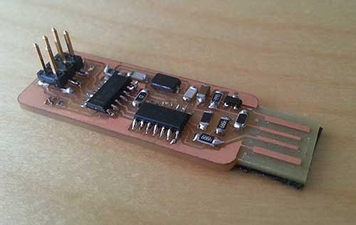
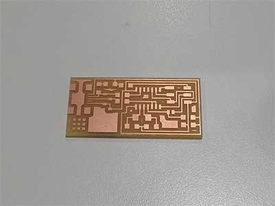
A few minutes later, the board was perfectly reproduced.
Then it was time to cut the board. To do this, I used a 1/32 mill with a depth of 1.8 (this time I set a margin of 0.3mm) and a speed value of 0.5.
5 minutes later I had my first FabISP board!
Welding
Stuffing the board with such small components was a complete new challenge for me. That's why I read and watched some welding videos before doing it.
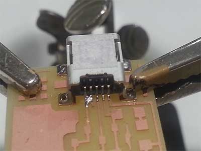
The first component I welded was the USB connector because it had the smallest pins. Initially I welded the legs of the connector in order to perfectly align the pins with the copper traces.
Everything was fine until I started joining those small connectors to the copper path. The first one was done without any problem, but while I was trying to do the same with the second one I made a solder bridge between the first two pins. A few attempts later I removed the bridge and realized that it couldn't happen again because I wasted a lot of time trying to fix the issue. I love working under pressure ;).
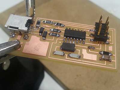
A few tries later I learnt that, in order to weld without such issues, I should heat the joint between the copper and the component before bringing the solder from the upper side of the component to get a clean and beautiful weld.
In a few minutes I finished mi first board.
Programming
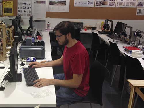
Programming the board was quite straightforward. Once I connected the board to the PC and checked that all the components were neither heating nor giving up smoke, I connected my board with a working FabISP.
I downloaded the firmware and followed the steps specified in the assignment.
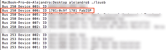
Finally, once I checked that the computer properly recognized the FabISP, I removed the jumpers.
FabISPlokey
Working with low power circuits might be very interesting for this project. The circuit may not have the same design or features, but the power consumption will be lower.
Reading about the different FabISP models I found the FabISPlokey. With this board I will be able to program 1.8V targets.
The process to build this FabISP was similar to the one described above. There was just one difference: in order to fit the board in the USB plug, I added a couple layers of scotch tape below the connector.