Fab Academy 2015
Fab Academy
How to Make Almost Anything...
How to Make Almost Anything...
This week we have to add an output device to a microcontroller board we've designed and program it to do something. In my case for this assignment, I will design a power output for LED lighting control, this will be the lighting system for my aquarium. In tests I will control only 1 LED (200mA), but in the future will be 20 LEDs (4 amperes).
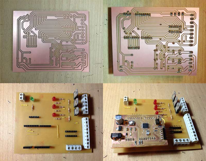
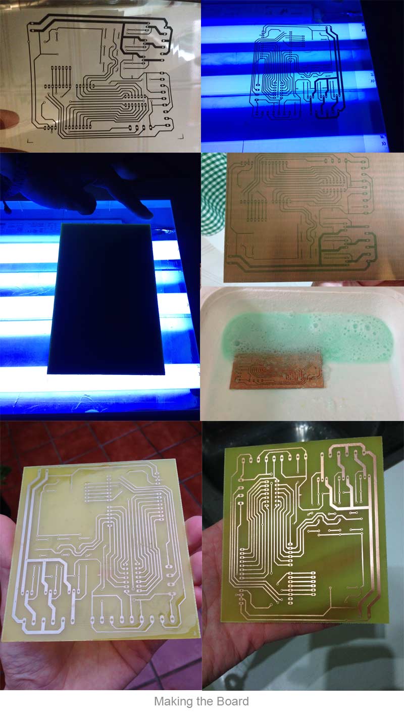
I am a remote FabLab student, this week I couldn't go to the FabLab, so I made this practice with the traditional method of insolation and acid, I have enough experience with the creation of PCBs using this technique so I have not problems handling hazardous components. Either way, I perform this practice again using the "MODELA" as soon as possible.
The Mosfet is a power transistor that not consume current on his gate, so it could be use like a switch. In my case, I'm going to use the Mosfet to control the LEDs. The mosfet that I'm ging to use can handle 50 amps, in my case I'm going to use less than 3 amps with each mosfet.
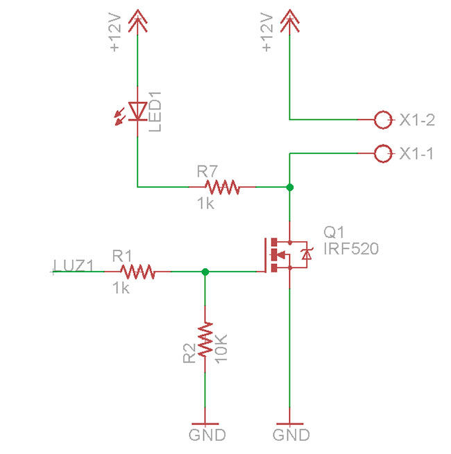
A very important part to avoid damaging the LED is the current limiter, in the common LED, this is compound by a resistor, buy this is only valid for low current LEDs, in my case, I'm going to use power LEDs who needs 200mA each one. To limit the current with 10 volts, I need a 50 Ohm resistor, buy this resistor must be 2 Watt resistor (only to limit the current in a LED), in my case I'm going to use 20 LEDs, so I need 40watt resistor (something unfeasible).
When using power LEDs, the limitation of current is done through this devices:
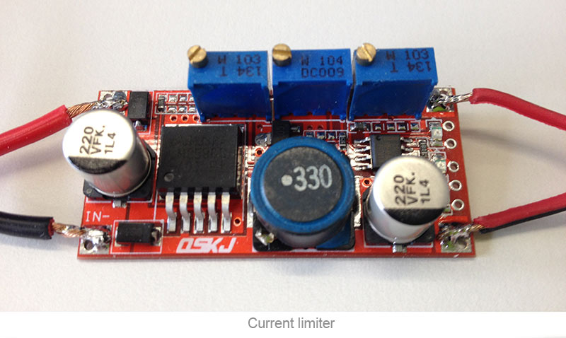
This device is specifically a battery charger but is used like a LED current limiter, as you can see, this board have 3 potentiometer for adjust the voltage, the output current and the input current.
As I mentioned above, I made this plate using a traditional manufacturing method, I applied ultraviolet light to the photosensitive board, then using hydrochloric acid, I remove the excess copper, leaving visible the traces. I will repeat this board as soon as possible using the Modela.
The program I loaded on the controller board is very simple, just what I've done to check the operation of the board. The program just turn on and turn off the LED with an interval of 5 seconds, in the future, to enable the LED will be implemented by a timer or a switch.
This example is very similar to that come by default with Arduino "blink"
			/*
			# This sample codes is for testing the power shield
			# Date: 20/04/2015
			*/

			#define SensorPin 0          //pH meter Analog Input 0
			#define led 9  //define led on pin 9

			void setup()
			{
				pinMode(led, OUTPUT);  //Establishes Led output
			}

			void loop()
			{
				digitalWrite(led,HIGH);  //turn on the led
				delay(5000);  //wait 5 sec.
				digitalWrite(led,LOW);  //turn off the led
				delay(5000);  //wait 5 sec
			}
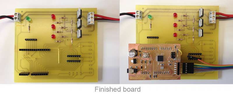
When I could, I remade the board using the modela the design is the same using previously.