Fabacademy2015 work by Loes Bogers is licensed under a Creative Commons Attribution-NonCommercial-ShareAlike 4.0 International License.

My first proposal was to create a steampunk inspired Insect or Bird Clock. Now it's more or less a useless movement machine, perhaps with clockwork abilities and/or interactions. I love this mechanical fantasy aesthetic and think that making a partly mechanical, partly digital clock can include many of the topics covered in the class. I want the machine to have old-fashioned mechanical look and movement like a traditional clock, and it could eg. come to life at every hour.
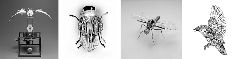
Inspiring projects: mechanical instect by Justin Gershenson-Gates, bird clock by Dukno Joon, mechanical bird drawing by KimLouise, paper bug by Soon.
And check out this wicked wicked project by U-Ram Choe, wicked....Thanks for the tip Alex!
It's this kind of motion I'd be looking for, gorgeous!This is Bussola by Jennifer Townley (all of her work is amazing).
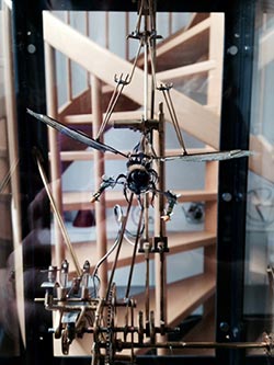
In week 4 I started making some studies on mechanic movement, how to design and engineer it. I've found some amazing examples to draw from like this bug war machine type thing by Leon van Opstal:
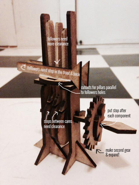
I started by recreating a waving movement using a handcrank system I found online. I worked with cardboard and failed miserably, the sizing was off and the material was too flimsy. I moved to MDF and had to start with some tests for snapfitting it right.
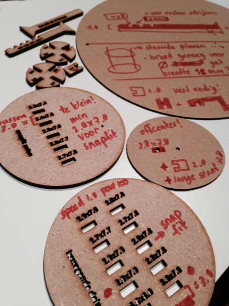
Summary useful summaries from the Making things Move book:
After the snapfit test with MDF I cut the designs again in 3mm MDF. I was very disappointed because some of the things I tested didn't fit in the end. Eg. the followers (moving poles on top), and the fact that the cams (round things moving on bottom) had to fit around a rectangular shaft wasn't great in the end (the shaft broke).
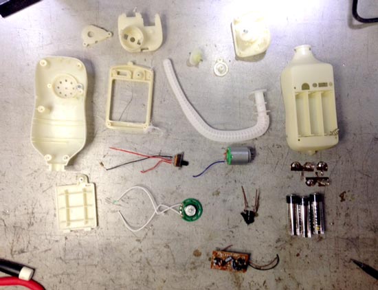
I've had this terribly scary toy for a while: it used to be a cat that rolls over by rotating it's tail. It makes creepy sounds too. I took it apart to understand a little how it works and to see if I could repurpose some components for my project. It's a chinese toy, and consists of: a battery pack and connectors, an LDR, a speaker, a motor, a bunch of gears, housing, a slideswitch, and a PCB.
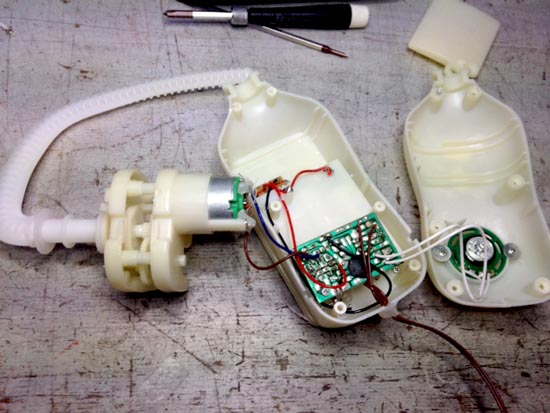
I tried to keep the toy working for as long as possible while breaking it apart, so I could udnerstand the wiring a bit. Of course the flimsy wires broke quickly but I could figure out how they were supposed to run.
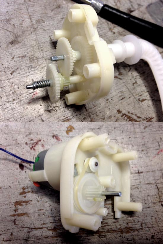
I expected to find a mosfet on the PCB because I read that you need them to operate motors. But there wasn't any of those, just a bunch of bidirectional transistors. I didn't know that they were both transistors but it's explained here. Other than that: loads of capacitors, some resistors etc. The mechanics of the gears around the motor looked really nice, I might be able to reproduce some of them for my own machine.
I will use the slideswitch and the motor to build a circuit for my own machine. By the looks of it, the motor is the same one that comes with an Arduino starter kit: 6-9V DC motor, that I should be able to run with an Arduino board or the ATtiny44, using a mosfet. Next step will be to breadboard it with an Arduino (I borrowed a surface mount mosfet from fablab and soldered wires to the legs), until I find a schematic that works and is compatible with the ATtiny44.
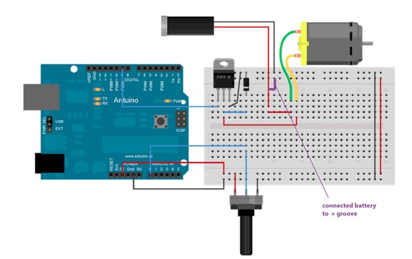
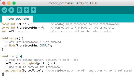
I found this article explains really well what components should be in such a circuit and what they do. It also explains how to use PWM to control the speed of the motor. Also this piece on different actuators was helpful. And this page on how to use MOSFETS. And finally this is a winner to get started: this tutorial explains a circuit with a variable transistor (potmeter) to control the speed of a DC motor . This will only let it run in one direction (no H-bridge necessary for that) but that's fine by me. I tried that tutorial with my arduino starter kit and a adjustable power supply: the motor runs beautifully with anything between 0.5V and 4.5V applied to it. With the potentiometer you can adjust the speed of the motor.
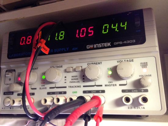
Note: our adjustable power supply is broken, it doesn't show the right values so you have to attach a multimeter to the current ports to see what it's actually giving out, then you set it to the right voltage. When it's right you turn on the output switch.
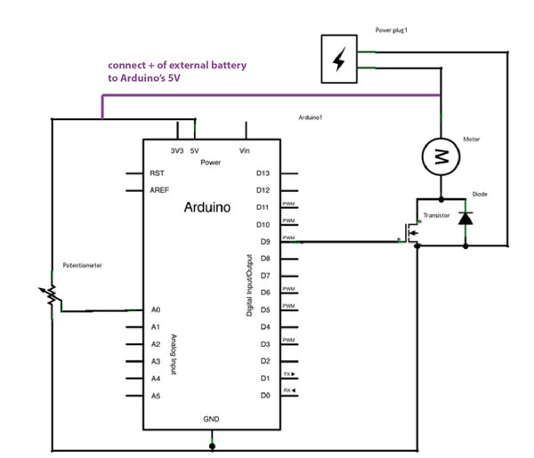
Then I also unplugged the USB cable to see if it would run without the power from my computer. I had to add one wire to the circuit and the schematic like this:
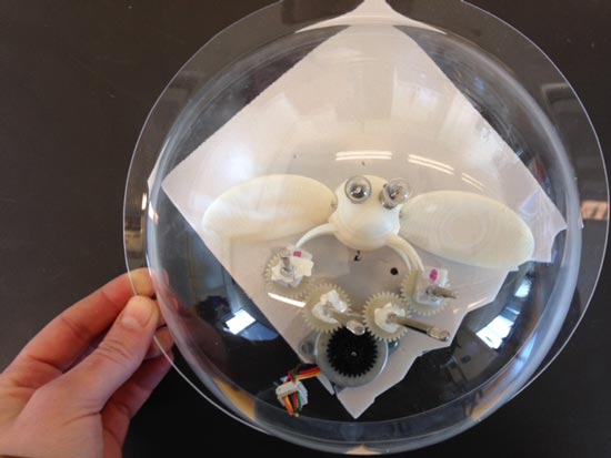
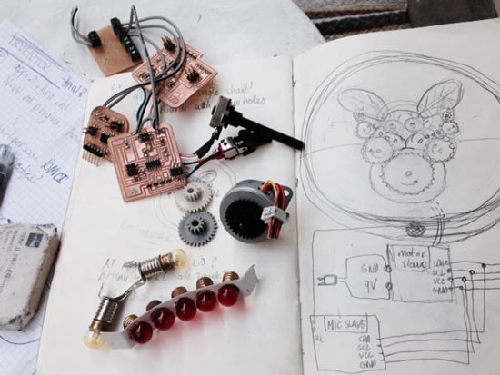
This is what the whole thing is supposed to look like: A bell glass jar in a wooden two-part frame that closes with a latch around the dome (so it can be mounted on the wall). There's a microphone sensor on the wooden frame, and inside is a bug with indandescent light bulbs for eyes, and a motor circuit with gears (entirely visible under transparent sheet of acrylic) that drives its wings when you blow into the mic.
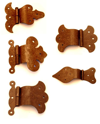
I want to go for an oldschoolish steampunk look so I will design the hinges and latches to put the bug and the thing together. I will design my own decorated gears that will get the kind of aesthetic I used for the bird kit.

As for the bug. It needs a lot of design work still, but I designed and prototyped a very quick and dirty version (very). To work out sizing, I need to see it and feel it to know what it should be. But it should definitely be more refined. For finishing I'd like to experiment a bit with overdoing an aceton polish a little bit: so that it looks like it's been deteriorating. Might be a terrible idea in terms of construction because there's a risk of deforming the screwholes, but I'll try one anyway.
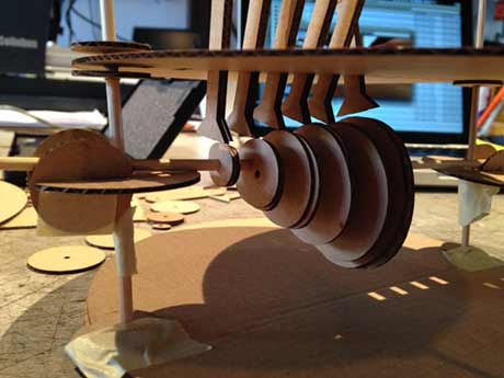
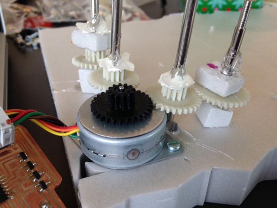
I'm waiiiiiting waiting waiting for the machine building week to come! But I don't want to wait too long so I just started doing some really rough hotglued improvised version to get an understanding of what such a construction would require and also to get a feel for the sizing of things. I used some off the shelf gears for this: luckily I found a set that fits my motor axis with a 2mm diameter. But naturally I would like to design my own and steampunk decorate the hell out of them.
I used the motor board from the output devices week to get the thing going. The most useful thing I learned from doing this is that the height of the position of the gears and the relative distance to the next gear is quite precise so I'd have to take care of that when making a construction kit.
Also, it's really useful to see firsthand what parts need to be fastened and secured, and which need space to move. In this example, the gears rotate around the axis but the axis itself doesn't move, there's some clearance there so I need to measure the diameters of the axes I'll use and their relative size compared to the hole in the gears.
Furthermore, the gears want to spin upwards along the shaft so I'll need a way to keep them down. Could be a screwhole on the axis, or create a transparent box. The transparent toplayer can hold everything together and it will also be good for stability. Just the camshafts will need to be outside the box to push the wings up and down.
Axes don't move, gears do so make sure to fasten them!
The size of the last gear in the row now determines how long the camshaft can be. In this case it's quite short but enough to see the effect with a test bug I'm printing at the moment. The camshaft could actually also have different shapes to create more jittering. Perhaps a square cam would be better (4 jitters in one revolution).
As for speed: there's two ways to control it: with the motor (seems happy enough driving these gears by the looks of it so far), OR with mechanics. in that case I would need to play more with the sizing of the gears and make the last one in the row smaller, so that it makes more revolutions with the same motor speed. Having a smaller end gear would mean making a smaller cam shaftin this example, but in the final thing I will trim down the axes so the camshaft can fly over the other gears without problems. This takes away the sizing restriction.
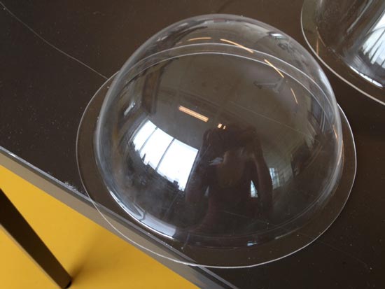
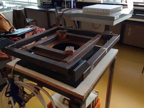
I was thinking hard about how to cast a bell glass dome for a cover, when I realized I have acces to a free dome blowing apparatus at work! The max size it can blow has a diameter of 250mm. And that can go at least 100mm high without problems.
Here's a really REALLY rough (hotglue forever) styrofoam proto thrown together to help me think about requirements, restrictions and materials. I'm grinning really hard when looking at the weird uglyness of it and that is totally the point. Reminds me of one of those really lazy pathetic bumblebees sort of half assed buzzing in the windowsill not knowing to live or die yet.