
Assignment: Make a machine, including the end effector. Document the group project and your individual contribution
Our group documentation can be found HERE [INSERT LINK] In order not to create another machine to end up on a machine graveyard, we decided to create a machine that Fablab Amsterdam doesn’t have yet, but would be useful. Our goal is the make a CNC hotwire cutter with 4 degrees of freedom.
I guess it*s normal but some contributions got lost along the way because we changed direction or made decisions to solve something otherwise. Anyway, here it is:
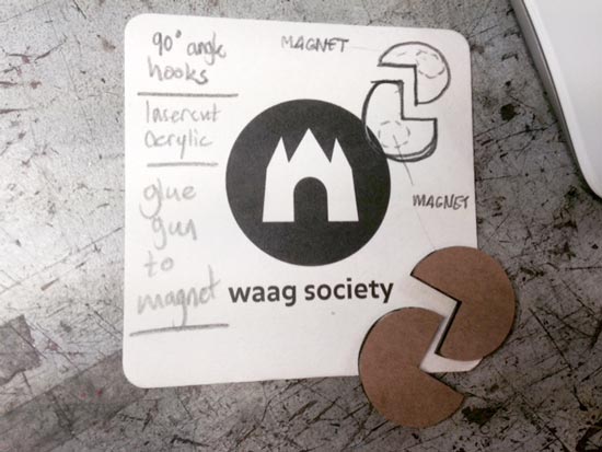
This was the original plan, but we didn*t implement it (yet). For now we are using doublesided tape and a wooden cutting bed. We had to create a bed to put the foam on and to keep it in place. We will be using an aluminium bed and are making two magnets with a 90 degree angle hook on top, to keep a square block of foam in place. The hotwire really melts through the material so should be enough to fasten the material easily. This is also how it’s done on other machines.
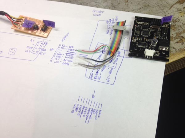
Natalia and I figured out the wiring of the netfab based on this documentation: http://fabacademy.org/archives/2015/doc/MachineMakingNotes.html as well as this overview that was really very helpful http://monograph.io/james/m-mtm The fuss about the wires was that first of all, the ribbons used in the examples are not the same as ours (10-wire ribbon vs our 9-wire ribbon with colors in the different order). Different connectors available. And not all the pins of the header on the netfab need to be connected. So we had to figure out what goes where. We looked at the schematics and board layouts provided in the documentation and mapped out the wiring to translate it to what we have in our fablab. We documented what should go where without actually making the cables yet because the sizing of the machine isn’t clear yet. But actually making them will be a 5 min job once we know.
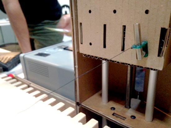
We prepared this and tested it separately, didn’t implement this into the entire system yet.
We decided to create end stops on the machine for safety, and got the supplies to build some switches into the machine so that when the end effector reaches the end of the stage, it will stop. We need two for each degree of freedom, so 8 in total.
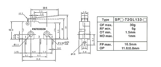
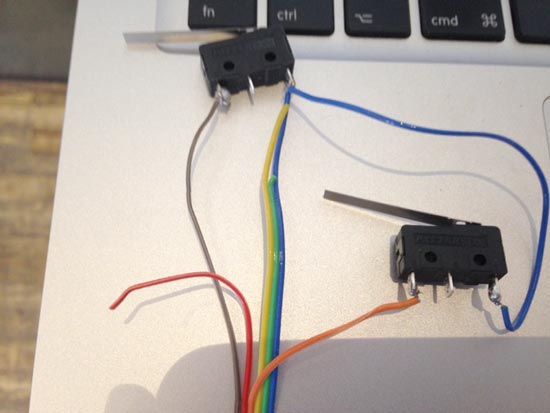
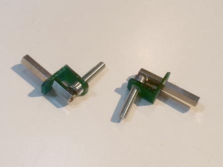
This is the switch
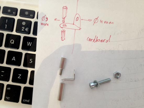
Note: Natalia found a useful page with a design for a part that can hold a switch and clip in place on the metal shafts.
Technical drawing of cut off switch:
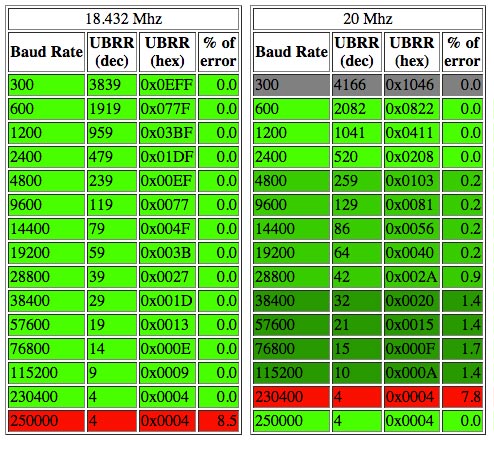
To get those to work accordingly we first wanted to design and and produce another node so that the switches can be connected to the network of the Gestalt nodes. We could do that with an ATMega328 as used on the Gestalt nodes. There’s an Arduino lib on the Github that supports this chip to work with the RS-485 protocol. We looked into it, and figured out how to work with the clock (see § below) and change things in the library to make it work with a 20mHz resonator instead of the recommended 16 or 18.4mHz (which we don’t have), but then decided against it, because we*d found a better solution (see plan B).
Then Zaerc had a clever suggestion: check in the schematic of the Gestalt nodes if you can repurpose the ISP headers as lines to the end switches. And BINGO! The MISO and SCK pins of the ISP header are only connected to the IC, so once the nodes are programmed, you can hook them up to something else and use thesame pins as an input (eg to measure whether your end effector has reached its limits :). Initially we put it on MISO and MOSI but MOSI has an LED and resistor attached to it, so SCK is better (ignore mistakes in pics below). Use Switches as NC (marked on component). Normally Closed closes the circuit when the button is not being pressed. So it will send signals all the time, UNLESS you press the switch (end effector reaches the end). That way you protect the system. If you’re machine breaks, eg. iif a cable breaks and makes a faulty connection the machine will also stop. If you do it the other way, you break a cable, the machine will push through the end because it doesn’t get a signal to stop anymore.
Switch 1: Connect NC pin to SCK on AVRISP header on node Connect GND pin to GND on AVRISP header on node Switch 2: Connect NC pin to MISO on AVRISP header on node Connect GND pin to GND on AVRISP header on node
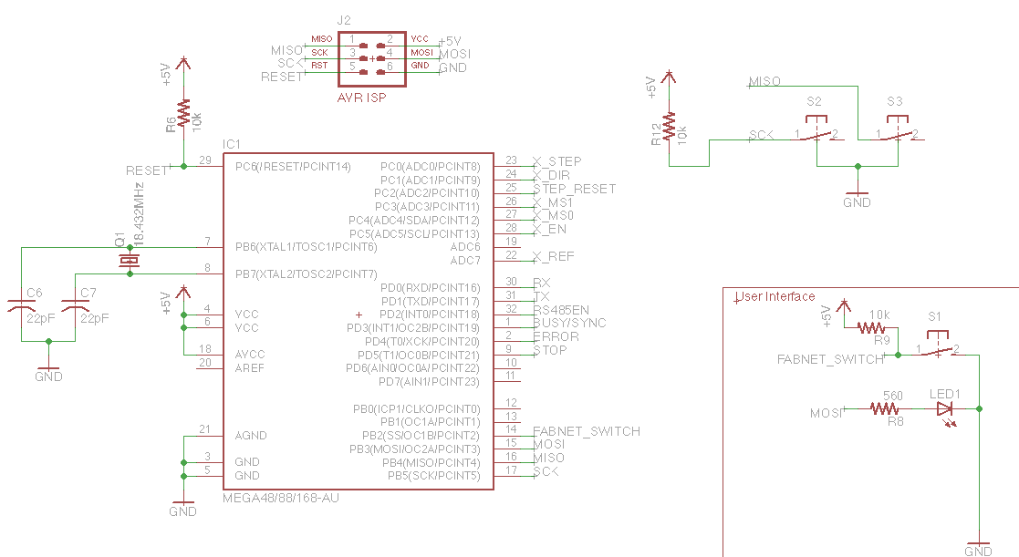
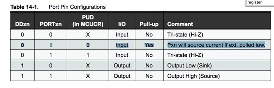
ATMega has internal pull-up resistors built into the chip. We need to enable them in the C-code by making sure the register of the MISO pin (PB3/PCINT3/pin15) and MISO pin (PB4/PCINT4/pin16) (DDRB, PORTB, PINB etc etc) are enabled as INPUTS, and make sure that the pullup resister is enabled. See table 14-1 in the ATMega328P datasheet
Joe and I set out to design and print the end effector - a non-conducting PLA part that will hold the hot wire and attach it to the moving part of the stage while avoiding any touching between the hot wire and the cardboard directly Cardboard would burn instantly, whereas the PLA can take the 100 degree celcius hot wire heat without melting. The sizing is a bit off. Could be improved by spacing the wires a bit further away from each others by making the PLA bit thicker but, this is the idea and it works. We hotglued it to the cardboard to keep it from turning. Two screws in the PLA part would be more elegant. The long hexagonal nut & bolt combo is an easy way to fasten the hot wire. You just wrap it around the bolt and screw the nut onto it.
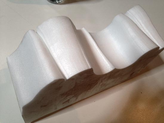
We also looked into making the hotwire extend to variable lengts using springs to really use the 4 degrees of freedom of the stages (wire needs to be longer for diagonal lines) But we*re still working on that. For our first test run to give proof of concept, we made a drawing to demonstrate 4 degrees of freedom, but in such a way that wouldn*t require varying lengths of the hotwire.
I also compiled all the documentation and pictures into a html page and posted it on the Amsterdam fablab page here
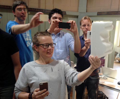
It*s ALIVE!